26
2.2 Batteries
A battery integration drawing and wiring schematic is included in the kit supplied with the product (except the
rack and F3U).
The battery temperature sensor must be placed as close to the battery as possible.
3 Connection
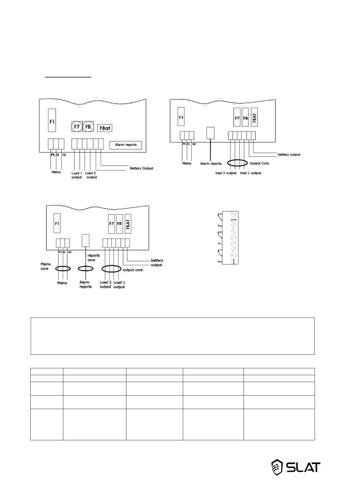
3.1 Connection diagram
50-75 W wiring 100-300 W wiring
400-600 W wiring Alarms reports wiring
* The cable tie included with all the products allows the mains cable to be secured to the mains terminal strip.
Important:
The openings provided in the cabinets must be used. Do not create additional openings as doing so
may casue the device to malfunction and voids the warranty, except locations on C38 and C85.
The connection of batteries on F3U/3U racks requires the use of cables with a length of less than 3m.
Core use table
C24-C48 C38-C85 Rack F3U Rack 3U - C180
50-75 W None None None -
100-150 W OUTPUT CORE to be
installed
OUTPUT CORE
pre-installed
OUTPUT CORE to be
installed
-
200-300 W OUTPUT CORE to be
installed
OUTPUT CORE
pre-installed
- OUTPUT CORE pre-
installed
400-600 W MAINS CORE +
REPORTS CORE +
OUTPUT CORE to be
installed
- - FILTER/MAINS CORE +
REPORTS CORE +
OUTPUT CORE pre-
installed
1
2
3
4
5
6
7
8
9
NO
NC
NO
NC
NO
NC
Mains
Battery
Output
NC : Normally Closed
NO : Normally Opened