4
3
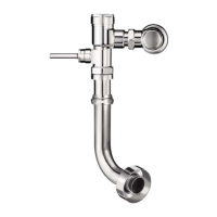
Install Vacuum Breaker Flush
Connection
VACUUM
BREAKER
TUBE
SPUD COUPLING
NYLON SLIP
GASKET
RUBBER
GASKET
SPUD FLANGE
A
Slide Spud Coupling, Nylon Slip Gasket, Rubber Gasket and Spud
Flange over Vacuum Breaker Tube.
B
Insert Tube into Fixture Spud.
C
Hand tighten Spud Coupling onto Fixture Spud.
VACUUM
BREAKER
TUBE
SPUD COUPLING
NYLON SLIP
GASKET
RUBBER
GASKET
SPUD FLANGE
SPUD COUPLING
NYLON
SLIP
GASKET
RUBBER
GASKET
SPUD FLANGE
MODELS 110/111,
115, 136
MODELS 120,
121, 122, 137
MODEL 180 MODEL 186
ELBOW FLUSH
CONNECTION
4A
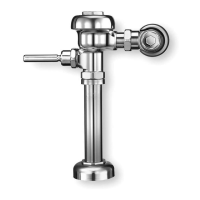
Install Flushometer
4B
Install Flushometer (Continued)
C
Align Flushometer Body and securely tighten first the Tailpiece
Coupling (1), then the Vacuum Breaker Coupling (2), and finally
the Spud Coupling (3). Use a wrench to tighten these couplings in
the order shown.
B
Align Flushometer directly above
the Vacuum Breaker Flush
Connection by sliding the
Flushometer Body IN or OUT as
needed. Tighten Vacuum Breaker
Coupling by hand.
A
Lubricate tailpiece O-ring with
water. Insert Adjustable Tailpiece
into Control Stop. Tighten
Tailpiece Coupling by hand.
Maximum adjustment of the Sloan Adjustable Tailpiece is
1/2" (13 mm) IN or OUT from the standard 4-3/4" (121 mm)
(centerline of Flushometer to centerline of Control Stop).
If roughing-in measurement exceeds 5-1/4” (133 mm),
consult factory for longer tailpiece.
NOTE
TAILPIECE COUPLING
CONTROL
STOP
1
FLUSHOMETER
BODY
VACUUM
BREAKER
COUPLING
2
ADJUSTABLE TAILPIECE
O-RING
G-44 FRICTION
RING
SPUD
COUPLING
3
C/L
FIXTURE
C/L
SUPPLY
VACUUM
BREAKER
FLUSH
CONNECTION
4-3/4”
(121 mm)
±1/2”
(13 mm)
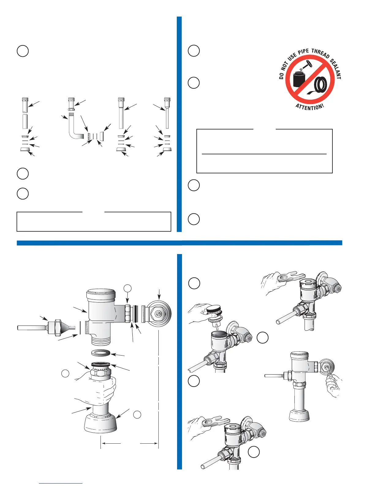
5
Flush Out Supply Line
A
Make sure Control Stop
is CLOSED and remove
Flushometer Cover.
C
Install Flushometer Cover wrench
tight. Open Control Stop to flush
supply line. Close Control Stop
and remove Flushometer Cover.
B
Lift out Piston Assembly.
D
Reinstall Piston Assembly and
Flushometer Cover. Tighten
Flushometer Cover wrench tight.
VACUUM
BREAKER
On valves furnished less vacuum breaker (XYV Variation) connect flush
tube to the bottom of the valve using the slip gasket supplied.
NOTE
HANDLE
ASSEMBLY
GASKET
D
If not installed, install Handle Assembly with Gasket to handle
opening on Flushometer Body. Tighten Handle Assembly securely.
VACUUM
BREAKER
REPAIR
KIT
 Loading...