Do you have a question about the Sloan 110 and is the answer not in the manual?
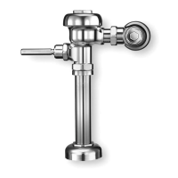
Diagrams showing critical installation dimensions for water closet flushometers.
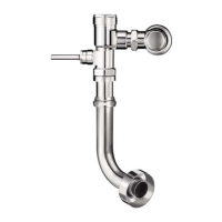
Diagrams showing critical installation dimensions for urinal flushometers.
Important notes regarding ADA guidelines for flushometer installation height.
Essential items and requirements to verify before installing the flushometer.
List of necessary tools for the correct installation of the flushometer.
Procedure for installing an optional sweat solder adapter onto the supply pipe.
Steps to install the cover tube, wall flange, and control stop to the supply pipe.
Connecting the vacuum breaker assembly to the fixture and flushometer.
Lubricating and inserting the adjustable tailpiece into the control stop.
Aligning and securely tightening the flushometer body couplings.
Procedure to flush the supply line and check for leaks after installation.
Adjusting the control stop for proper flush and installing the vandal-resistant cap.
Guide to diagnose and resolve common flushometer operational problems.
Chart identifying flushometer pistons, models, and capacities.
Guidelines for cleaning chrome and special finishes to maintain luster.
Comprehensive list of flushometer components and their part numbers.
| Brand | Sloan |
|---|---|
| Model | 110 |
| Category | Water System |
| Language | English |