3
PRIOR TO INSTALLATION
Before you install the GEM•2
®
Flushometer, be sure the items listed below
are installed. Also, refer to the rough-in diagram on Page 2.
• Closet/urinal fixture
• Drain line
• Water supply line
Important:
• ALL PLUMBING SHOULD BE INSTALLED IN ACCORDANCE WITH
APPLICABLE CODES AND REGULATIONS.
• WATER SUPPLY LINES MUST BE SIZED TO PROVIDE AN ADEQUATE
VOLUME OF WATER FOR EACH FIXTURE.
• WHEN INSTALLING A FLUSHOMETER, IT IS IMPORTANT THAT THE
FLUSH MODEL MATCHES THE REQUIREMENTS OF THE PLUMBING
FIXTURE.
• FLUSH ALL WATER LINES PRIOR TO MAKING CONNECTIONS.
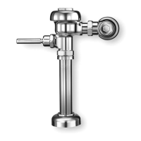
The Sloan GEM•2
®
Flushometer is designed to operate with 10 to 100 psi
(69 to 689 kPa) of water pressure. THE MINIMUM PRESSURE REQUIRED
TO THE VALVE IS DETERMINED BY THE TYPE OF FIXTURE SELECTED.
Consult fixture manufacturer for minimum pressure requirements. Most Low
Consumption water closets (1.6 gpf/6.0 Lpf) require a minimum flowing
pressure of 25 psi (172 kPa).
TOOLS REQUIRED FOR INSTALLATION
• Straight blade screwdriver
• Sloan A-50 Super-Wrench™, Sloan A-109 Plier Wrench or smooth
jawed spud wrench
With the exception of Control Stop Inlet, DO NOT use pipe sealant
or plumbing grease on any valve component or coupling!
!!! IMPORTANT !!!
Protect the chrome or special finish of Gem•2 Flushometers — DO
NOT USE toothed tools to install or service these valves. Use a
Sloan A-50 Super-Wrench™, Sloan A-109 Plier Wrench or smooth
jawed spud wrench to secure all couplings. Also see “Care and
Cleaning” section of this manual.
!!! IMPORTANT !!!
This product contains mechanical and/or electrical components
that are subject to normal wear. These components should be
checked on a regular basis and replaced as needed to maintain
the valve’s performance.
!!! IMPORTANT !!!
If you have questions about how to install your Gem•2 Flushometer,
consult your local Sloan Representative or call Sloan Installation
Engineering Department at:
1-888-SLOAN-14 (1-888-756-2614) OR 1-847-233-2016
1
Install Optional Sweat Solder
Adapter (only if your supply pipe
does not have a male thread)
A
Measure from finished
wall to C/L of Fixture
Spud. Cut pipe 1¼"
(32 mm) shorter than
this measurement.
Chamfer O.D. and I.D. of
water supply pipe.
WATER SUPPLY PIPE
FINISHED WALL
1-1/4”
(32 mm)
C/L OF
FIXTURE
SPUD
SWEAT
SOLDER
ADAPTER
B
Slide Threaded Adapter
fully onto pipe.
C
Sweat solder the Adapter
to pipe.
Thread Control Stop onto pipe.
Tighten with a wrench.
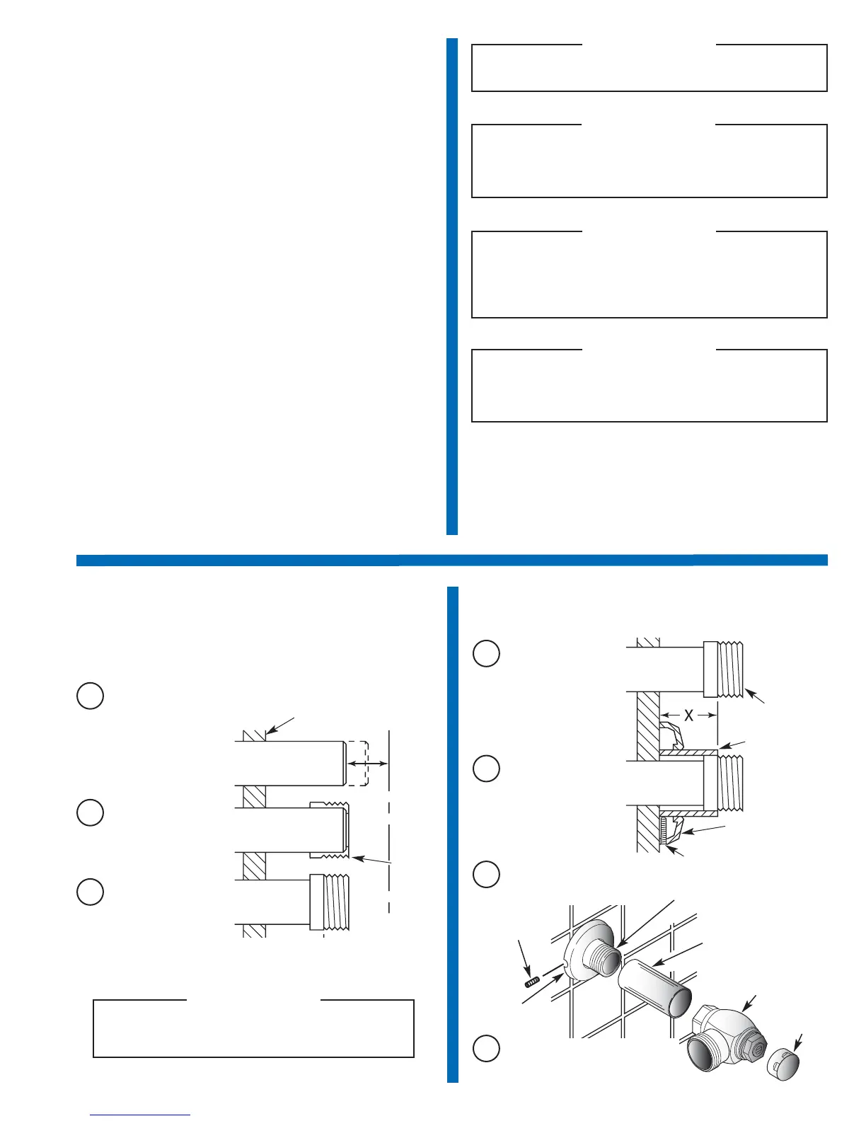
2
Install Cover Tube, Wall Flange
and Control Stop to supply pipe
BAK-CHEK
®
CONTROL STOP
COVER TUBE (COVERING
TUBE AND CAST SET SCREW
AVAILABLE IN “YBYC” SWEAT
SOLDER KIT)
IRON PIPE NIPPLE OR COPPER PIPE
WITH SWEAT SOLDER ADAPTER
SET SCREW
SUPPLY
FLANGE
WATER
SUPPLY PIPE
SWEAT
SOLDER ADAPTER
COVER TUBE
WALL
FLANGE
SET SCREW
A
Measure from finished
wall to first thread of
Adapter or threaded
supply pipe (dimension
“X”). Cut Cover Tube to
this length.
B
Slide Cover Tube over
pipe. Slide Wall Flange
over Cover Tube until
against wall.
C
Tighten Set Screw with a 1/16” hex
wrench. DO NOT install Vandal
Resistant Stop Cap at this time.
D
With the exception of Control Stop Inlet, DO NOT use pipe
sealant or plumbing grease on any valve component or
coupling!
!!! IMPORTANT !!!
CONTROL
STOP CAP
Never open Control Stop to where the flow from the valve
exceeds the flow capability of the fixture. In the event of a
valve failure, the fixture must be able to accommodate a
continuous flow from the valve.
!!! IMPORTANT !!!
 Loading...