Repair Parts and Maintenance Guide
78
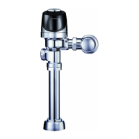
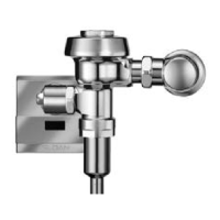
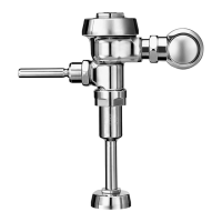
Sensor Flushometers
The information contained in this document is subject to change without notice.
IMPORTANT: The OPTIMA PLUS
®
ushometer is engineered for quiet
operation. Excessive water ow creates noise, while too little water ow
may not satisfy the needs of the xture. Proper adjustment is made when
plumbing xture is cleansed after each ush without splashing water out
from the lip AND a quiet ushing cycle is achieved.
Never open Control Stop to where the ow from the valve exceeds the ow
capability of the xture. In the event of a valve failure, the xture must be
able to accommodate a continuous ow from the valve.
ATTENTION INSTALLERS: With the exception of the control stop inlet,
DO NOT USE pipe sealant or plumbing grease on any valve component or
coupling! To protect the chrome or special nish of Sloan ushometers,
DO NOT USE toothed tools to install or service these valves. Use our A-50
Super-Wrench
™
or other smooth-jawed wrench to secure couplings.
Regulations for low consumption xtures (1.6 gpf/6.0 Lpf closets and
1.0 gpf/3.8 Lpf urinals) prohibit use of higher ush volumes.
1. Sensor fl ashes continuously only when user steps within range.
A. Unit in start-up mode; no problem. This feature is active for the
rst 10 minutes of operation.
2. Valve does not fl ush; sensor not picking up user.
A. Range too short; increase the range.
B. Optima Plus installed on a high rough-in xture (beam is shooting
over the user’s head). Install the EBV-46-A beam de ector (black
modules only).
3. Valve does not fl ush; sensor picking up opposite wall or surface,
or only fl ushes when someone walks by. Red light fl ashes
continuously for fi rst 10 minutes even with no one
in front of the sensor.
A. Range too long; shorten range.
B. Sensor is picking up mirror or highly re ective wall or surface in front
of xture. Install Optima Plus
®
slightly “off-center” (2 to 5 degrees) to
eliminate direct re ection off of mirror or opposite wall or surface.
4. Valve does not fl ush even after adjustment.
A. Range adjustment potentiometer set at full “max” or full “min”
setting. Readjust potentiometer away from full “max” or “min” setting.
B. Batteries completely used up; replace batteries.
C. Problem with electronic sensor module; replace electronic sensor
module.
5. Unit fl ashes 4 quick times when user steps within range.
A. Batteries low; replace batteries.
6. Valve does not shut off.
A. By-pass ori ce in diaphragm is clogged with dirt or debris, or by-pass
is clogged by an invisible gelatinous lm due to “over-treated” water.
Remove diaphragm and wash under running water. Replace with new
diaphragm if cleaning does not correct the problem.
B. Dirt or debris fouling stem or ex tube diaphragm. Remove ex
tube diaphragm and wash under running water.
C. Problem with solenoid. If cleaning does not correct the problem,
replace with new isolated solenoid operator.
7. Not enough water to fi xture.
A. Wrong Optima Plus ex tube diaphragm installed; i.e., 1.0 gpf
urinal installed on 3.5 gpf closet xture. Replace with proper
diaphragm assembly.
B. Enlarged by-pass in diaphragm. Replace with ex tube
diaphragm kit.
C. Control stop not adjusted properly. Readjust control stop.
D. Inadequate volume or pressure at supply. Increase water pressure
or supply ( ow) to valve. Consult factory for assistance.
8. Too much water to fi xture.
A. Control stop not adjusted properly. Readjust control stop.
B. Wrong Optima Plus ex tube diaphragm installed; i.e., 3.0 gpf model
installed on 1.0 or 1.5 gpf urinal xture. Replace with proper Optima
Plus diaphragm assembly.
C. Dirt in diaphragm by-pass. Clean under running water or replace
with new ex tube diaphragm.
9. Men’s room closet bowls unfl ushed.
A. Closet being used as urinal. Angle sensor slightly off xture
centerline to detect standing person in front of xture.
BATTERIES
When required, replace batteries with four (4) alkaline type AA batteries.
CARE AND CLEANING OF CHROME AND SPECIAL FINISHES
DO NOT USE abrasive or chemical cleaners to clean ushometers as they
may dull the luster and attack the chrome or special decorative nishes.
Use ONLY mild soap and water, then wipe dry with clean cloth or towel.
While cleaning the bathroom tile, the ushometer should be protected
from any splattering of cleaner. Acids and cleaning uids can discolor
or remove chrome plating.
When assistance is required, please contact
Sloan Technical Support at: 1-888-SLOAN-14 (1-888-756-2614).
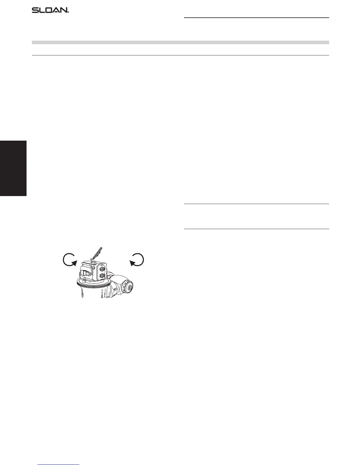
TROUBLESHOOTING GUIDE
COUNTERCLOCKWISE
CLOCKWISE
Increases
Range
Repair Parts and Maintenance Guide
Optima
®
Flushometers
Repair Parts and Maintenance Guide
79
Sensor Flushometers
The information contained in this document is subject to change without notice.
15
14
18A
2
18B 18C
19A
19B 19C
19D
19D 19D
3
1
5
8
7A
17
12
11
9
13
4
16
6
7
20
Repair Parts and Maintenance Guide
Optima
®
Sloan Flushometer
PARTS LIST
Item
No. Code No. Part No. Description
1. 0325298 EBV-189-A Cover/Ring/Sensor Assembly - Water Closet
0325299 EBV-190-A Cover/Ring/Sensor Assembly - Urinal
0325239 EBV-198-A Cover/Ring/Sensor Assembly - Water Closet
w/ Zurn ring
0325240 EBV-199-A Cover/Ring/Sensor Assembly - Urinal w/Zurn ring
2. 0325241 EBV-192-A Cover Assembly
3. N/A EBV-168 Locking Ring - Plastic inner cover only –
Use 3325089, EBV-1010-A
0305843 EBV-14 Locking Ring - Metal inner cover only
0305843 EBV-30-A Locking Ring - for Zurn valves
4. 3325450 EBV-129-A-C Electronic Module - Water Closet
3325451 EBV-129-A-U Electronic Module - Urinal
5. 3325089 EBV-1010-A Metal Inner Cover Repair Kit
Includes Items Nos. 3, 5, 6 and 7
6. 0325171 EBV-134 Cover Rest Plate
7. 3325453 EBV-136-A Solenoid
7A. 3325456 EBV-145-A Inside Cover Assembly (includes solenoid
EBV-136-A) Does not replace Plastic Inner Cover.
Use Item No. 5
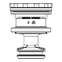
8. SEE CHART NEXT PAGE Flex Tube Diaphragm Assembly
9. SEE CHART NEXT PAGE Flush Volume Regulator
10. 3325814 EBV-1017 Handle Cap Kit
11. 0325107 EBV-91 Range Adjustment Tool
12. 0305823 EBV-22 Strap Wrench
13. 0325159 EBV-137 7/64” Hex Wrench
14. 3308785 H-634-AA 1” (25 mm) Sweat Solder Kit
3308788 H-636-AA 3/4” (19 mm) Sweat Solder Kit
15. 3308386 H-700-A 1” (25 mm) Bak-Chek
®
Control Stop
3308384 H-700-A 3/4” (19 mm) Bak-Chek
®
Control Stop
16. 3308840 H-573-A Stop Cap
17. 0305381PK EBV-36-A Valve Body *
18A. 5323007 V-500-AA 1-1/2” (38 mm) x 9” (229 mm) Vacuum Breaker
(Model 8110/8111)
0323014 V-500-AA 1-1/2” (38 mm) x 13 1/2” (343 mm) Vacuum
Breaker (Model 8113)
0323019 V-500-AA 1-1/2” (38 mm) x 23” (584 mm) Vacuum Breaker
(Model 8115)
0323021 V-500-AA 1-1/2” (38 mm) x 26” (660 mm) Vacuum Breaker
(Model 8116)
18B. 5323006 V-500-AA 1-1/4” (32 mm) x 9” (229 mm) Vacuum Breaker
(Model 8180)
18C. 5323005 V-500-AA 3/4” (19 mm) x 9” (229 mm) Vacuum Breaker
(Model 8186)
19A. 0306145 F-56-A 1-1/2” Spud Coupling Assembly
(Models 8110, 8115 & 8116)
19B. 0306142 F-55-A 1-1/4” Spud Coupling Assembly (Model 8180)
19C. 0306102 F-54-A 3/4” Spud Coupling Assembly (Model 8186)
19D. SEE SLIP JOINT GASKETS AND RINGS TABLE ON NEXT PAGE
20. 3323192 V-551-A Vacuum Breaker Repair Kit
* Part number varies with valve model variation; consult factory.
Earlier model with
A-3 body
A-3 Body
10
10
372626_Master_Book_ccg.indd 76 9/18/17 7:52 AM
 Loading...