Repair Parts and Maintenance Guide
70
Sensor Flushometers
The information contained in this document is subject to change without notice.
Repair Parts and Maintenance Guide
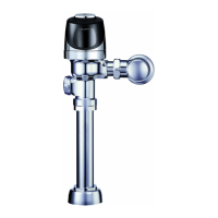
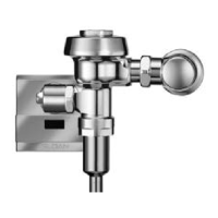
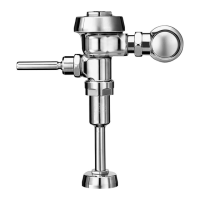
G2 Optima
®
Flushometer
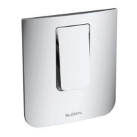
Back View
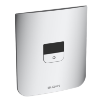
Front View
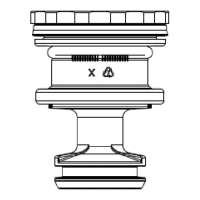
SOLENOID REPLACEMENT
Code No. Part No. Description
3325453 EBV-136-A Solenoid operator
For G2 Optima Plus
®
modules (identi ed by a
blue module).
Note. Verify that rubber insert is installed
Close up
1. Turn off water and relieve pressure by loosening Tailpiece
coupling and re-tighten. Loosen and remove top screws along
with the outer cover assembly.
5. Make sure all O-rings (2) are installed on the grey End cap
of the new Isolated Operator. Install Isolated Operator by
threading it (clockwise) into the Housing. Tighten with fi ngers
beyond just snug.
2. Disconnect wire clip from battery door and remove module from
inner metal cover assembly.
6. Mount module on inner cover assembly. Reconnect the plastic
clip on the battery door.
3. Remove Solenoid by turning counter clockwise. Remove any
remaining O-rings or parts in orifi ce.
7. Assemble outer cover assembly.
4. Remove black plastic Housing from the threaded end of new
Isolated Operator by unscrewing (counterclockwise). It is normal
to fi nd fl uid inside this housing.
8. Turn on water at control stop. Installation complete.
Repair Parts and Maintenance Guide
71
Sensor Flushometers
The information contained in this document is subject to change without notice.
Repair Parts and Maintenance Guide
G2 Optima
®
Flushometer
When G2 Optima Plus
®
has approximately 4,000 ushes left, the same red
light that appears at start-up will ash four (4) times quickly whenever an
object is detected. When this occurs, we recommend changing the batteries
as follows:
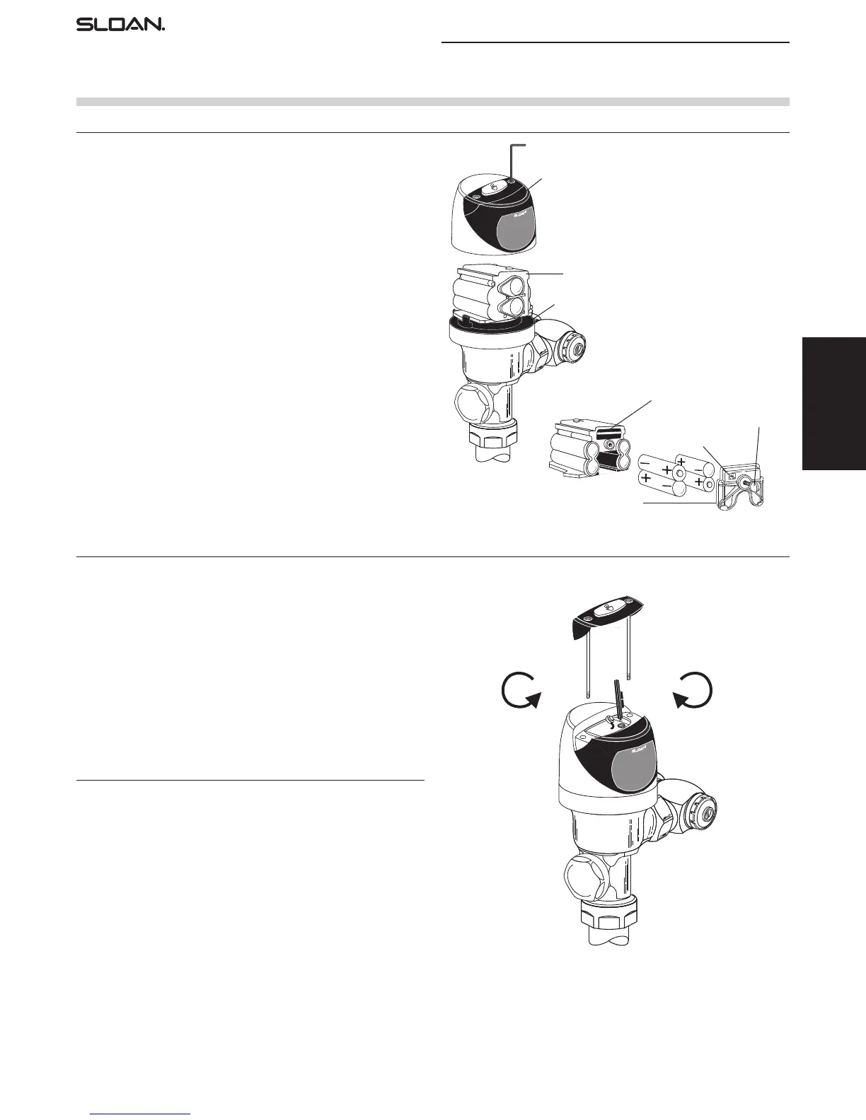
When required, replace batteries with four (4) alkaline type AA batteries.
Note: Water does not have to be turned off to replace batteries.
Loosen the two (2) screws on top of unit. Remove the complete cover
assembly. Lift the sensor module from its plate. Unplug the electrical
connector from battery compartment cover. Loosen the retaining screw on
battery compartment cover and remove battery compartment cover. Install
four (4) alkaline type AA batteries exactly as illustrated at right.
Install battery compartment cover and secure with retaining screw. Make
certain that battery compartment cover is fully compressed against gasket
to provide a seal; Do not overtighten. Plug the electrical connector into the
battery compartment cover. Reinstall the sensor module onto the plate.
Reinstall the complete cover assembly onto the plate. Tighten the two
(2) screws on top of the unit.
7/64” ALLEN WRENCH
COVER ASSEMBLY
PLATE
SENSOR MODULE
SENSOR MODULE (BACKSIDE SHOWN)
BATTERY COMPARTMENT COVER
ELECTRICAL CONNECTOR
RECEPTACLE
RETAINING SCREW
COUNTERCLOCKWISE
CLOCKWISE
Increases Range
The G2 Optima Plus has a factory set sensing range:
Water closet models – 22” to 42” (559 mm to 1067 mm)
Urinal models – 15” to 30” (381 mm to 762 mm)
The Factory setting should be satisfactory for most installations.
If the range is too short (i.e., not picking up users) or too long (i.e., picking
up opposite wall or stall door) the range can be adjusted.
Note: Water does not have to be turned off to adjust range.
Loosen the two screws on top of the unit. Remove the override button.
Remove the rubber plug from top of electronic sensor module to uncover
the potentiometer.
RANGE ADJUSTMENT PROCEDURE
For the rst ten (10) minutes of operation, a visible red light ashes in the
sensing window of the G2 Optima Plus ushometer when a user is detected.
This visible red light feature can be reactivated after ten (10) minutes by
opening and closing the battery compartment door or holding the override
button for (1) minute.
Check the range by stepping toward the unit until the red light ashes,
indicating the sensor’s detection of a user. Adjust the range potentiometer
screw located on top of the sensor module a few degrees CLOCKWISE to
increase the range or a few degrees COUNTERCLOCKWISE to decrease the
range. Repeat this adjustment until the desired range is achieved.
Always determine the sensing range with metal cover and lens
window on top of the unit.
Important: Adjust in small increments only! Range potentiometer
adjustment screw rotates only 3/4 of a turn; DO NOT over-rotate.
When range adjustment is satisfactory, replace the rubber plug. Reinstall
override button and tighten the two screws on top of the unit.
RANGE ADJUSTMENT (ADJUST ONLY IF NECESSARY)
BATTERY REPLACEMENT
372626_Master_Book_ccg.indd 69 9/18/17 7:52 AM
 Loading...