Repair Parts and Maintenance Guide
74
Sensor Flushometers
The information contained in this document is subject to change without notice.
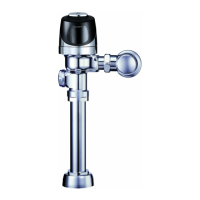
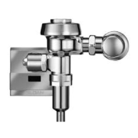
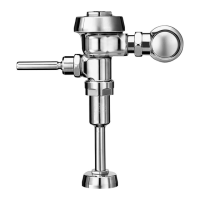
Optima
®
Flushometers
Repair Parts and Maintenance Guide
18
17
21
16A
16B
20
19
15
14
10
9
9A
12
11
13
13A
22
23
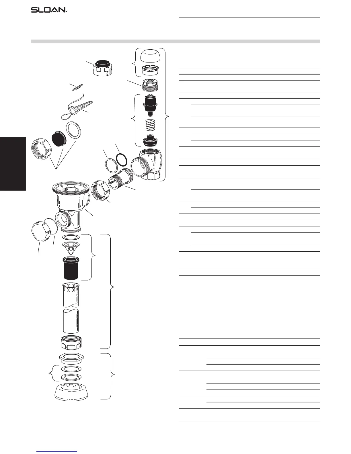
Valve Body (Part number varies with
valve model variation; consult factory)
OTHER VALVE COMPONENT PARTS
Item
No. Code No. Part No. Description
9. 3325814 EBV-1017-A Handle Cap — Metal
9A. 0311042 K-46 Blind Nut Gasket
10. 3325815 EBV-1018-A Handle Cap — Metal Coupling/Plastic Hole Cap –
OBSOLETE
11. 3323182 V-651-A Vacuum Breaker Repair Kit
12. 3393004 V-600-AA 3/4” (19 mm) x 9’’ (229 mm) CP Vacuum Breaker
3393006 V-600-AA 1-1/4” (32 mm) x 9’’ (229 mm) CP
Vacuum Breaker
3393007 V-600-AA 1-1/2’’ (38 mm) x 9’’ (229 mm) CP
Vacuum Breaker
13. 0306125 F-5-AW 3/4’’ (19 mm) CP Spud Coupling
0306140 F-5-AU 1-1/4” (32 mm) CP Spud Coupling
0306146 F-5-AT 1-1/2’’ (38 mm) CP Spud Coupling
13A. SEE SLIP JOINT GASKETS AND RINGS TABLE BELOW
14. 0308676 H-550 CP Stop Coupling
15. 0308801 H-551-A CP Adjustable Tailpiece 2-1/16’’ (52 mm) long
16A. 5308696 H-553 O-ring — 24 per package
16B. 5308381 H-552 Locking ring – 12 per package
17. 3308386 H-700-A 1’’ (25 mm) Screwdriver Bak-Chek
®
Stop CP —
complete
3308384 H-700-A 3/4’’ (19 mm) Screwdriver Bak-Chek
®
Stop CP —
complete
18. 3308853 H-541-A Control Stop Repair Kit
†
3/4” H-600/H-540 only
3308856 H-543-A Control Stop Repair Kit
‡
19. 0308612 H-622 CP Bonnet
†
0308843 H-577 CP Bonnet 3/4” H-600/H-540 only – OBSOLETE
‡
20. 3308772 H-1010-A Vandal Resistant Control Stop Cap Assembly
†
3308790 H-1009-A Vandal Resistant Control Stop Cap Assembly
‡
21. 3325816 EBV-1019-A 3/4’’ (19 mm) Decorative Stop Cap
3308866 H-574 1’’ (25 mm) Decorative Stop Cap
ACCESSORIES
22. 0325107 EBV-91 Trimpot Adjustment Screwdriver
23. 0305823 EBV-22 Disposable Strap Wrench
† For use w/H-700-A 1’’ & 3/4’’ and H-600-A 1’’ screwdriver Bak-Chek
®
control stops,
also marked with Quiet Stop II
‡ For use w/H-600-A 3/4’’ urinal screwdriver Bak-Chek
®
control stops, also marked with Quiet Stop II.
ITEM 13A. SLIP JOINT GASKETS AND RINGS
Size Code No. Part No. Description
1-1/2” 5306058 F-3 Red Friction Ring
5322001 VBF-5 Black Slip Joint Gasket
0319086/5319086 S-30 Flexible Seat
0319079 S-21 Rigid Seat (rubber over brass)
1-1/2” x 1-1/4” 0396062 F-105 Slip Joint Gasket – Rigid
1-1/4” 5306057 F-3 Red Friction Ring
5322176 VBF-5 Black Slip Joint Gasket
0307052/5307052 G-21 Rigid Seat (rubber over brass)
1” 5306056 F-3 Red Friction Ring
5306115 F-5 Black Slip Joint Gasket
3/4” 5306055 F-3 Red Friction Ring
5306113 F-5 Black Slip Joint Gasket
Repair Parts and Maintenance Guide
75
Sensor Flushometers
The information contained in this document is subject to change without notice.
Optima
®
Flushometers
Repair Parts and Maintenance Guide
The electronic and optical improvements of the G2
Optima Plus
®
have been incorporated into the electronic
modules for use with older Optima Plus products.
Optima Plus
®
modules can be identi ed by color.
Old style modules are black and have a wire that runs
along the side of the unit.
G2 modules are blue and have a wire only on the back
of the unit.
There are now only two electronic module assembly variations for use with
older Optima Plus valves:
EBV-146-A-U Urinal
EBV-146-A-C Water closet
This chart cross references the part numbers and code numbers of our new
electronic modules over from our old module numbers.
The modules include the solenoid, inner cover and electronic module.
These modules are for use with older Optima Plus and Regal Pro
®
Optima
Plus
®
valves only.
ELECTRONIC SENSOR
MODULE
Use To Replace
Code No. Part No. Description Old Part No.
0325177 EBV-146-A-U Electronic — 0.5 gpf/1.9 Lpf Urinal EBV-26-A-U-0.5
Module
0325177 EBV-146-A-U Electronic — 1.0 gpf/3.8 Lpf Urinal EBV-26-A-U-1.0
Module
0325177 EBV-146-A-U Electronic — 1.5 gpf/5.7 Lpf Urinal EBV-26-A-U-1.5
Module
0325177 EBV-146-A-U Electronic — 3.5 gpf/13.2 Lpf Urinal EBV-26-A-U-3.5
Module
0325176 EBV-146-A-C Electronic — 1.6 gpf/6.0 Lpf Closet EBV-26-A-C-1.6
Module
0325176 EBV-146-A-C Electronic — 2.4 gpf/9.0 Lpf Closet EBV-26-A-C-2.4
Module
0325176 EBV-146-A-C Electronic — 3.5 gpf/13.2 Lpf Closet EBV-26-A-C-3.5
Module
0325176 EBV-146-A-C Electronic — 4.5 gpf/17.0 Lpf Closet EBV-26-A-C-4.5
Module
Note: EBV-26-A modules are no longer available. Use the EBV-146-A-U or EBV-146-A-C module shown.
When Optima Plus has approximately 4,000 ushes left, the same red light
that appears at start-up will ash four (4) times quickly whenever an object
is detected. When this occurs, we recommend changing the batteries.
On Optima Plus, shut off water and relieve pressure.
Separate locking ring, cover and diaphragm from electronic sensor module.
Loosen retaining screw on battery compartment door and remove battery
compartment door. Install four (4) alkaline, AA batteries exactly as
illustrated. Install battery compartment door and secure with retaining
screw. Make certain that battery compartment door is fully compressed
against gasket to provide a seal; do not overtighten.
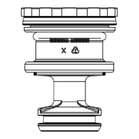
In early 2003 Sloan introduced the ex tube diaphragm kit into the Optima
Plus. This design completely replaced the old Optima Plus diaphragm
kit that featured the metal shaft with the quad Ring. This change further
improved the reliability of the Optima Plus as it replaced a wearable dynamic
seal (the Quad Ring) with a non-moving static O-ring seal.
The ex tube diaphragm kit also features Sloan’s exclusive dual- lter
diaphragm. The dual- lter diaphragm helps to protect the valve from water-
borne sediment that can cause the valve to stick open and run on. The
dual- lter diaphragm is also made from Sloan’s Permex
®
synthetic rubber
material for resistance against chloramines and other water treatment
chemicals.
The fl ex tube diaphragm can be used to replace all generations of
Sloan Optima Plus
®
diaphragm kits. The same fl ex tube diaphragm
kits are used in the G2 Optima Plus
®
valve.
ELECTRONIC MODULE ASSEMBLY CHART
FLEX TUBE DIAPHRAGM ASSEMBLY
BATTERY REPLACEMENT
372626_Master_Book_ccg.indd 72 9/18/17 7:52 AM
 Loading...