HM-20-IS-en-10 SMA Solar Technology AG
Installation when not using the integrated measuring unit
If an SMA Energy Meter is installed at the grid-connection point and is not to be
replaced by the Sunny Home Manager 2.0, the Sunny Home Manager 2.0 can
also be operated without the measuring unit being enabled.
1. Connect the line conductor L1 and the neutral conductor to the voltage supply
of the Sunny Home Manager 2.0.
2. Select the SMA Energy Meter present as the purchased-electricity and feed-in
meter in Sunny Portal (see Section "Defining the Energy Meter at the Grid-Con-
nection Point").
Measuring the PV production power (single-phase / three-phase) up to
63 A
In PV systems with inverters from other manufacturers or hybrid systems with SMA
inverters, the integrated measuring unit can also be used for measuring the PV pro-
duction power. In this case there must already be an SMA Energy Meter installed
at the grid-connection point (see "Installation when not using the integrated measur-
ing unit").
1. Connect the Sunny Home Manager 2.0 to the common connection point of all
inverters in the household grid.
2. Select the Sunny Home Manager 2.0 as the PV production meter in Sunny Por-
tal (see Section "Defining the Energy Meter at the Grid-Connection Point").
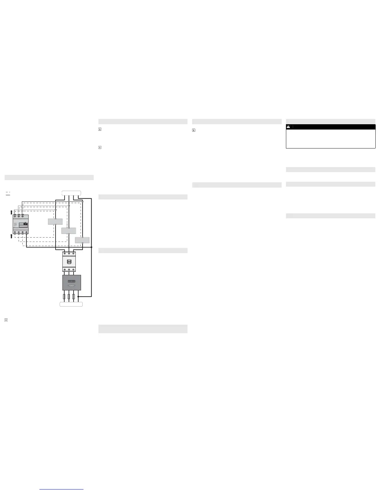
The following figure shows a connection example in TN and TT grid configurations
in the case of installation at the grid-connection point. For exact connection specifi-
cations, contact your electric utility company.
Additionally required material (not included in the scope of delivery):
☐ 3 x current transformer
☐ Connection cables for current transformers
Procedure:
1. Connect one current transformer to each line conductor L1, L2 and L3.
2. On each current transformer, connect one connection cable for current measure-
ment to each of the secondary current terminals (k/S1 and l/S2). Observe the
permitted connection cross-section of the
Sunny Home Manager 2.0
(see Sec-
tion "Technical Data"):
3. Connect the connection cables for current measurement (dashed gray line) to
the
Sunny Home Manager 2.0
. Observe the prescribed torque for screw termi-
nals (see Section "Technical Data").
4. Connect the connection cables for voltage measurement (solid gray line) to the
Sunny Home Manager 2.0
. Observe the prescribed torque for screw terminals
(see Section "Technical Data").
Connect the connection cables for voltage measurement to the corresponding line
conductors.
Additionally required material (not included in the scope of delivery):
☐ 1 x network cable
Recommended cable types:
• SF/UTP, S-FTP, S/UTP, SF/FTP, S/FTP, S-STP
Procedure:
1. Connect the network cable to the network terminal of the SunnyHomeManager
2.0.
2. Connect the other end of the network cable to a router / network switch.
Requirements:
☐ The PV system must be in operation.
☐ All devices must be in operation and connected to the
Sunny Home Manager 2.0 via a router / network switch.
☐ Devices that support the EEBus industry standard must be connected to the
Sunny Home Manager 2.0 (see technical information "SMA SMART HOME -
Home appliance energy management using EEBus").
☐ DHCP must be active for the router (see router manual).
Procedure:
1. Cover the Sunny Home Manager 2.0 with a cover or the contact protection of
the subdistribution.
2. Switch the power supply to the subdistribution back on.
☑ The LEDs on the Sunny Home Manager 2.0 light up during the startup proce
-
dure. All devices in the local network will be recognized automatically.
3. Register all devices in Sunny Portal.
Sunny Portal serves as the user interface of the Sunny Home Manager 2.0. There-
fore, you must register the Sunny Home Manager 2.0 in Sunny Portal.
Requirements:
☐ The PV system and all devices in the local network must be in operation (see Sec-
tion "Commissioning").
☐The registration ID (RID) and the identification key (PIC) from the
Sunny Home Manager 2.0 type label must be available.
Procedure:
1. Call up www.SunnyPortal.com and select [PV System Setup Assistant].
or
Call up www.SunnyPortal.com/Register.
☑ The PV System Setup Assistant opens.
2. Select [Next].
☑ The User Registration page opens.
3. Follow the instructions of the PV System Setup Assistant.
4. After completing the registration, configure further settings in Sunny Portal
(see the Sunny Home Manager 2.0 manual at www.SMA-Solar.com):
• Add automatically recognized devices
• Configure the load profile of the automatically recognized devices
• Enter the operator data
• Enter the PV array power
• Enter the feed-in tariff, self-consumption tariff and electricity tariff
• Configure settings for PV system monitoring.
Requirements:
☐ You must be logged in to Sunny Portal as an Installer.
Procedure:
1. Select Configuration > Device Overview in the page and menu selection.
2. In the Sunny Home Manager 2.0 row and the Properties column, select the
properties symbol.
3. Select [Edit].
4. In the Meter Configuration area, select the desired feed-in and purchased
electricity meter or PV production meter from the drop-down list (see Section
"Electrical Connection for Applications up to 63 A" for selection).
5. Select [Save].
Default settings
• To reset the Sunny Home Manager 2.0 to the default settings, press down and
hold the reset button using a sharp object for two to six seconds.
☑ LEDs flash first green and then red.
Restart
• To restart the Sunny Home Manager 2.0, press down and hold the reset button
using a sharp object for longer than six seconds.
☑ LEDs go out. The status LED then glows red constantly during system startup.
Pressing down and holding the reset button for less than two seconds has no effect.
The Sunny Home Manager 2.0 status LED flashes red.
It may be that DHCP has not been activated in the router.
• Activate DHCP in the router.
The Sunny Home Manager 2.0 performance LED flashes green.
An error has occurred. The error has already been reported to Sunny Portal.
• Check the system logbook in the Sunny Portal system and follow the recommend-
ed actions.
The Sunny Home Manager 2.0 performance LED glows red.
An error has occurred. The error has not yet been reported to Sunny Portal.
• Ensure that the Sunny Home Manager 2.0 is connected to the Internet via the
local router. If the connection is correct, the error information will be transmitted
to Sunny Portal.
• Check the system logbook in the Sunny Portal system and follow the recommend-
ed actions.
The Sunny Home Manager 2.0 performance LED flashes red.
There is no connection to Sunny Portal.
• Ensure that the Sunny Home Manager 2.0 is connected to the Internet via the
local router. If the connection is correct, energy data and error information will
be transmitted to Sunny Portal.
During registration, the PV System Setup Assistant can not find a
Sunny Home Manager 2.0, event though the RID and PIC have been
correctly entered.
It is possible that the Sunny Home Manager 2.0 is not connected to the router cor-
rectly.
• Ensure that the Sunny Home Manager 2.0 is connected to the router correctly.
It is possible that there is no voltage supply to the Sunny Home Manager 2.0. In this
case, all LEDs on the Sunny Home Manager 2.0 will be off.
• Ensure that the Sunny Home Manager 2.0 has a voltage supply (see section on
electrical connection).
It is possible that the registration procedure was previously initiated but not complet-
ed.
• Reset the Sunny Home Manager 2.0 (see Section "Resetting the
Sunny Home Manager 2.0").
Procedure:
1. Remove all connected conductors from the Sunny Home Manager 2.0.
2. Remove the Sunny Home Manager 2.0 from the top-hat rail. To do so, tilt the the
lower edge of the Sunny Home Manager 2.0 forwards and lift the
Sunny Home Manager 2.0 off of the top-hat rail.
• Dispose of the Sunny Home Manager 2.0 in accordance with the locally appli-
cable disposal regulations for electronic waste.
The software licenses for the installed software modules are contained in the
Sunny Home Manager 2.0 software. Upon connecting the
Sunny Home Manager 2.0 with a web browser, you will find the licenses at the fol-
lowing address: http://IP_address/legal_notices.txt.
The IP address (e.g. 192.168.1.120) will be assigned by your router for the
Sunny Home Manager 2.0.
You will find further information on determining the IP address in your router docu-
mentation.
If you experience any technical problems with our products, please contact Service.
The following data is required in order to provide you with the necessary assistance:
• Serial number of the Sunny Home Manager 2.0
• Type and serial number of the SMA products
• Error description
• Firmware version
SMA Solar UK Ltd.
Milton Keynes
+44 1908 304899
SMA Online Service Center:
www.SMA-Service.com
SMA Australia Pty Ltd.
Sydney
Toll free for Australia: 1800 SMA AUS
(1800 762 287)
International: +61 2 9491 4200
International SMA Service Line
Niestetal
00800 SMA SERVICE
(+800 762 7378423)
Version: 2017-01-27
Copyright © 2017 SMA Solar Technology AG. All rights reserved.
ELECTRICAL CONNECTION FOR APPLICATIONS > 63 A
Recommendations for the current transformer
SMA Solar Technology AG recommends current transformers designed for a
secondary current of 5 A. The current transformers should have at least accu-
racy class 1.
 Loading...

