-09- -06-
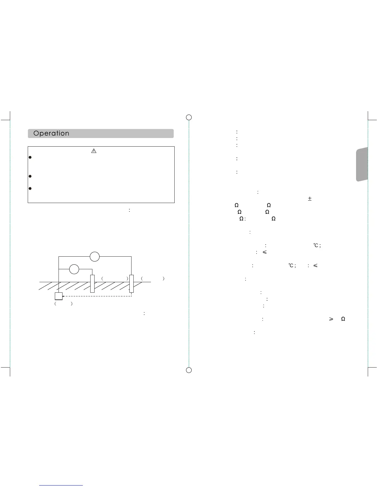
Voltmeter
V
~
Constant Current Generator
P Potential C Current
V=Rx X I
E Earth
Rx=V/I
E3 Error arising from temerature difference
E4 Error arising from different serial medium
E5 Error arising from different resistance
between pin and assistant connection
E6 Error arising from fluctuation of system
frequency
E7 Error arising from fluctuation fo system
voltage.
6. Max operating error
max operating error in measure range: ( 30%):
Within 2 : 0.5~1.999
Within 20 : 2~19.99
Within200 20~199.9
7. Measuring mode .all levels are continuous measurement.
8. Operating environment temperature: 0~40
relative humidity 85%RH(no fog)
9. Storage condition temp: -20~60 RH 75%rh(no fog)
10. Power supply 9V DC R6P (SUM-3)x6
11. Overload protection
earth resistance range 200V AC(10 seconds)
Earth voltage Range 300V AC (30 seconds)
12. Insulation resistance (500v wire to the housing) 5m
13. Resistant voltage (wire to the housing) 3700v ac 1 minute
without jump spark
When measuring the earth resistance with the unit, a voltage
up to 50V is generated between terminal Eand terminal C
which may shock to human.
For earth voltageage measuring, do not apply voltagemore
than 220V to avoid damage of the unit.
For earth resistance measuring, do not apply voltage to the
wire terminal
1. Measuring principle(as shown in figure)
The earth resistance value comes from that bycalculation of
the alternative current between terminal C and terminal E
andthe potential difference between terminal E and terminal
P in formula: RX=V/I
2. Precise measurement(with provided test wire)
a. Pin the terminal P and C into earth and aligned with the
ground device in spacing 5 to 10 meters between, and
connect them as shown in the followng:
(note: make sure the soil to be pinned is wet, water shall be
injected if the soil is dry or sanded.)
Warning
Rx=V/I
Need To know
Before use
 Loading...