-07- -08-
Operation sketch
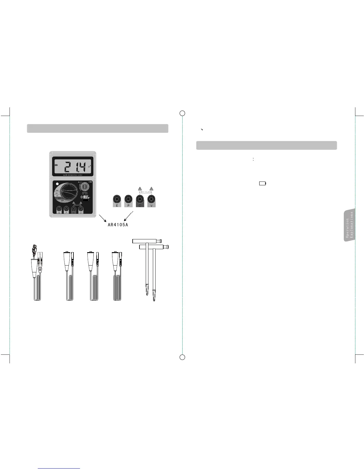
Appearance and components
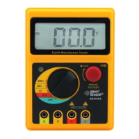
1.Battery voltage check
Turn on the unit, the LCD displays all info for once, and
backligh is on, then return to the selected level, if the
battery icon on LCD is “ ” , that means low battery, it is
necessary to replace the battery with fresh one,otherwise
the unit cannot work properly.
2. Connecting test pin:
Insert the pin with clip into the corresponding connector
in the unit, with terminal E to the green wire, P to yellow,
and C to red; or connect terminal P and C with the quick
test wire(for simple test);loose connection will affect the
measure result
2 Operation instruction
Before measurement
Auxiliary
Earth Spike
Green
Wire
Yellow
Wire
Red
Wire
Simplified
Test wire (red0)
AR4105A