-09- -06-
unit is on adjusting status. Then, increase or decrease the sound velocity to
the data you want by pressing “ ” and “ ”,and this data will be automatically
stored into current sound velocity memory unit. After that, press “ VEL” to
confirm new sound velocity, and the icons of “VEL” and “m/s” stop blinking.
press “VEL” once more, the “VEL” and “m/s” will keep blinking, indentifying the
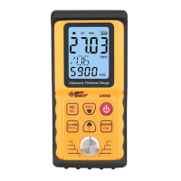
3.2 Calibration
A calibration should be made for every replacement of transducer or
batteries, this operation is sufficiently important to assure the measuring
precision. If necessary,this step should be repeated. Pressing “CAL” for
2 seconds, LCD displays “CAL”, indicating that the unit is on calibration
status, vertical bar displayed circularly on the left of LCD. put few provided
coupling agent on the stan-dard sample block to couple the transducer and
the sample block. Until the LCD display 4.0mm indicating the calibration
is completed. After calibration, sound velocity will back to your selected
value, and ready to measurement.
Calibration accomplished
3.7 Low battery indication
When icon flashes, please replace the batteries for further mea-
surement.
3.8 LCD back light & Automatic power off
Before turn on the gauge, hold pressing “ CAL ”, and press ON/OFF
button to turn on, the back light will active, every operation will turn on
the back light for 7 seconds until press ON/OFF to turn off the unit.
If no any operation for 2 minutes, the gauge will turn off automaticly
and the back light function will be cancelled.
4. Measurement Tips
4.1 Cleaning surface
Before measuring, the dust, dirt, rusting and grease etc that adheres
on the hardware/workpiece must be removed off and cleaned.
4.2 Decreasing the roughness of surface
Too rough surface may result in measure error/ fault reading. Please
try to make the surface smooth by milling, polishing, filling or using high
viscosity coupling agent.
4.3 Rough machining surface
The regular tiny texture/slots resulting from rough machining process
may cause error, and the compensation method is the same as in 4.2,
adjusting the angle between the crosstalk segregating board of the
transducer ( a metal membrane crossing the detector bottom centre) and
linear texture/slots (parallel or vertically) may also get a better result.
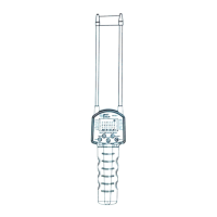
4.4 Measuring the surface of cylindrical parts
When measuring the material of cylindrical parts, like pipe 、oil tub etc,
it is critical to select the angle between the crosstalk segregating board
of the transducer and axis of the measured material. In simple terms,
couple the transducer and measured material, keep the crosstalk
segregating board of the transducer and axis of the measured material
parallel or vertical, wave the transducer slowly and perpendicularly along
the axis of the measured part. The reading on the screen will be changed
orderly, select the smallest one as the exact thickness.
Velocity adjustment Velocity revision
Calibration statu
 Loading...