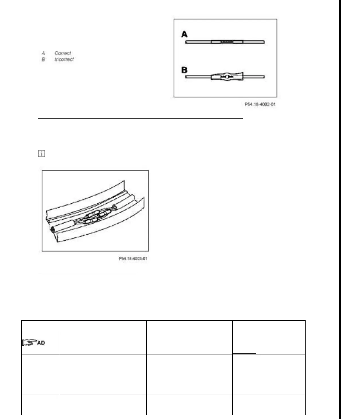
Fig. 30: Identifying Correct And Incorrect Position Of Soldered Point
Courtesy of MERCEDES-BENZ OF NORTH AMERICA.
10. Apply axial solder connector to the lines and wrap repaired area round with fabric tape.
The axial solder connectors must not lie directly above one another.
Fig. 31: Wrapping Repaired Area
Courtesy of MERCEDES-BENZ OF NORTH AMERICA.
CONTROL UNIT FLASHING - AR54.21-P-0012MCU
MODEL 451.3/4
Flashing
1 Connect STAR DIAGNOSIS
Connect STAR DIAGNOSIS
and read out fault memory
AD00.00-P-2000-
04MCC
2 Enter vehicle identification
number in
Diagnosis Assistance system
and open main menu with
"Button F2"
3 Select menu "Systems" in
main menu and confirm with
2010 Smart Fortwo Passion
2009 ACCESSORIES & BODY, CAB Electrical System, Equipment & Instructions - Fortwo (Cabrio)
15 октября 2019 г. 19:12:10 Page 32 © 2011 Mitchell Repair Information Company, LLC.

 Loading...