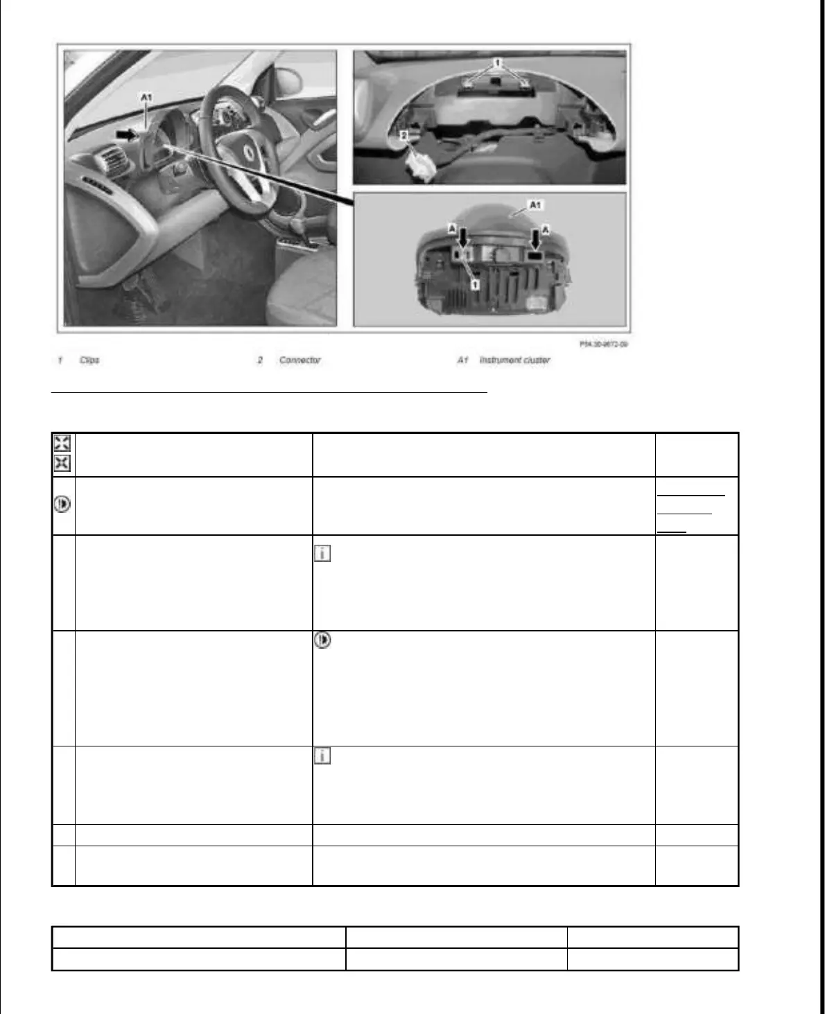
Fig. 39: Identifying Instrument Cluster, Clips And Connector
Courtesy of MERCEDES-BENZ OF NORTH AMERICA.
PARTS ORDERING NOTES
Remove/install
Notes on avoiding damage to
electronic components due to
electrostatic discharge
AH54.00-
P-0001-
01A
1
Pull the instrument cluster (A1) in
the direction of the arrow out of
the dashboard upper section until
the connector (2) on the instrument
cluster (A1) is accessible
Check position of clamps (1). When removing
the instrument cluster (A1) there is the danger that
the clamps (1) can fall through the openings
(arrows A) in the instrument cluster (A1).
2
Unlock connector (2) on the
instrument cluster (A1), detach
and remove instrument cluster
(A1) backwards
Clamps (1), which have fallen into instrument
cluster (A1) when removing, must be got out again
otherwise a short circuit in the instrument cluster
can occur (A1). This must only take place through
the opening a (arrow A). Disassembling the
instrument cluster (A1) is not permissible.
3
Remove clamps (1) on top part of
dashboard or on instrument cluster
(A1)
Installation: The clamps (1) are to be replaced
by the clamps (1) listed in the Parts ordering notes
table. Insert new clamps (1) in the top part of the
dashboard.
4 Install in the reverse order
5
Set clock in the instrument cluster
(A1)
Part no. Designation Quantity
A 203 988 28 78 Clamp 2
2010 Smart Fortwo Passion
2009 ACCESSORIES & BODY, CAB Electrical System, Equipment & Instructions - Fortwo (Cabrio)
15 октября 2019 г. 19:12:11 Page 43 © 2011 Mitchell Repair Information Company, LLC.

 Loading...