PREPARATION
Before installing SwitchLinc Lite, please familiarize yourself with the following and take the necessary
precautions listed here:
• Be sure that power to the load being controlled has been disconnected by removing the fuse or
turning the circuit breaker off. Installing SwitchLinc Lite with the power on may expose you to
dangerous voltages and may damage the product.
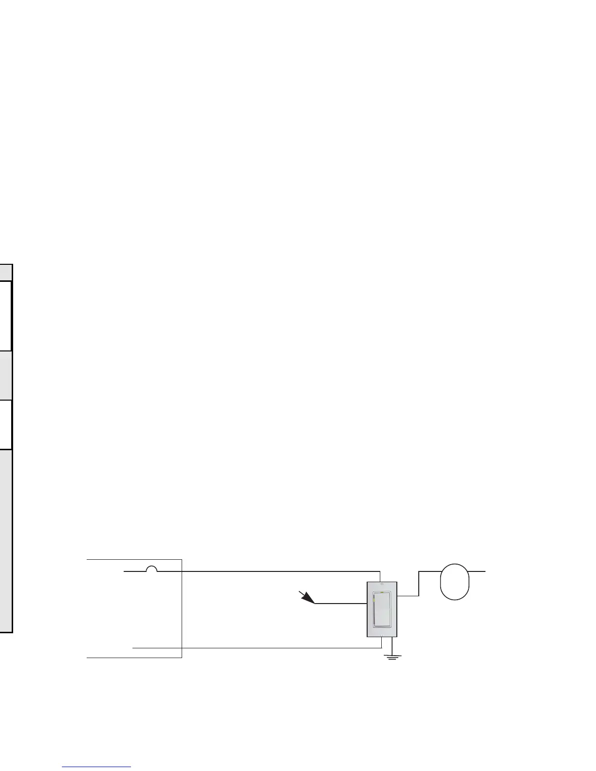
• Refer to the SwitchLinc Wiring Diagrams below to determine the wire colors of the connections
to SwitchLinc Lite. Note: All SwitchLinc Lites require a neutral connection.
• Wiring for 3-way, 4-way, & up switch circuits follow conventional (standard, non-remote) wiring
practice (plus the requirement for a neutral). Wiring “slave” switches requires the Line (Black)
wire be accessible and be on the same 110Vleg of the house wiring. The Grey wire on the
“slave” switch is to be connected to NEUTRALONLY. If neutral is not available, cap the Grey
wire (which simply causes the LEDnot to function).
• SwitchLinc Lite may feel warm during operation. The amount of heat generated is within U.L.
approved limits and poses no hazards. To minimize heat build-up, ensure that the area surround-
ing the rear of the SwitchLinc Lite has adequate ventilation (i.e., clear away excess insulation).
• Installation should be performed only by a qualified electrician, or by a homeowner who is
familiar and comfortable with electrical circuitry.
• Follow all routine safety precautions.
INSTALLATION
1. Remove the power from the existing switch/device.
2. Remove the faceplate from the existing switch/device.
3. Unscrew and pull the device out of the wallbox.
4. Disconnect the wires from the device.
5. Using a wire tester or voltmeter, identify and mark "Hot", “Neutral”, “Ground”, and “Traveler” (if
applicable) wires that were connected to the device.
6. Before making any connections to SwitchLinc Lite, FIRMLYPRESS SWITCHLINC LITE’S
ROCKER BOTTOM UNTILYOU HEAR ACLICK. A“System Off” sticker will be exposed on
the top of the rocker.
7. Orient SwitchLinc Lite so the LED is at the top, and make connections according to the “Switch-
Linc Wiring Diagram” below. Wire “slave” switches according to the “SwitchLinc Multi-Way
Wiring Diagram” on page 4.
3
SETTING GLOBAL(HOUSE-WIDE) OPTIONS
Disable Program
(Prevents accidental programming of SwitchLinc settings for all SwitchLincs in the home)
Transmit the following PLC sequence: M16, O16, P16, N16, P16
(Re-)Enable Program (default)
Transmit the following PLC sequence: N16, M16, O16, P16, P16
POWER RESTORE
SwitchLinc Lite will return the lighting circuit being controlled to its last brightness level when
power is restored after a power outage.
6
Main Panel
120VAC
Line
Neutral
Red
Ground
Load
SwitchLinc 2-Way
(Model 1181 or 1182)
Neutral
SwitchLinc Wiring Diagram
White
Light
Fixture
(s)
Yellow
Black
cap this lead
SwitchLinc Lite
(Model 2384)
Problem Possible Cause Solution
TROUBLESHOOTING & TECHNICALSUPPORT
Light comes ON too Ramp rate may be set Increase ramp rate if desired
slowly or goes OFF too slow
too slowly when
SwitchLinc is
tapped (manually)
SwitchLinc will not SwitchLinc may be in Re-enable Program mode, or perform
take programming Program Disable mode a Factory Reset to reset SwitchLinc
of ramp rate, etc. to factory defaults
SwitchLinc is locked Surge in power line Reset SwitchLinc by pressing bottom of
up or working rocker until it clicks into System
only intermittently Off mode, then release
LED is not visible Circuit breaker is off Turn circuit breaker on or connect fuse
and/or SwitchLInc
is not controlling SwitchLinc is in the Snap top of SwitchLinc into operating
the light System Off position mode
Insufficient load Increase load to meet minimum load
requirements
Incomplete (open) wire Check wallbox wires to ensure all
connection in wallbox connections are tight and no bare
wire is exposed
Incomplete (open) wire Check fixture to ensure all connections
connection at fixture are tight and no bare wire is exposed
 Loading...