Do you have a question about the SMC Corporation LECSA series and is the answer not in the manual?
Outlines warranty terms, disclaimers, and compliance requirements for product usage.
Crucial safety instructions to avoid electric shock hazards during operation and maintenance.
Important guidelines to prevent fire hazards related to installation and electrical connections.
Safety instructions to prevent personal injury during operation and handling.
Instructions for safe transportation and proper installation of the equipment.
Guidelines and precautions for correctly wiring the driver and servo motor.
Procedures for adjusting parameters and performing test runs for proper operation.
General usage guidelines, including emergency stop circuits and motor shaft handling.
Procedures for addressing potential hazardous conditions and ensuring safety.
Recommendations for storing the servo motor for extended periods to maintain its condition.
Information on maintenance schedules and component replacement, like electrolytic capacitors.
General advice on operating equipment according to the manual and installing safety guards.
Information on the limited write cycles of the EEP-ROM and potential failure modes.
Disclaimer regarding SMC's liability for damages caused by factors not attributable to SMC products.
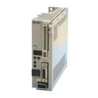
Introduces the LECSA series AC servo, its capabilities, and features.
Illustrates the functional blocks of the servo motor system for various control modes.
Details the electrical, environmental, and physical specifications of the driver.
Lists the functions of the servo system and refers to their detailed explanations.
Explains how to define the model code for the driver and option models.
Lists the compatible combinations of drivers and servo motors.
Identifies and explains the various parts and connectors on the driver.
Shows a configuration diagram including auxiliary equipment like filters and contactors.
Specifies the required installation direction and clearances for the driver and control box.
Provides instructions to prevent foreign materials from entering the driver.
Details how to manage cable stress to prevent damage and ensure proper connection.
Lists periodic checks recommended for maintenance and inspection.
Lists parts with a defined service life and their replacement guidelines.
Explains the main and control circuit power supply connections and safety precautions.
Provides examples of I/O signal connections for different control modes.
Details the signal explanations and power-on sequence for the power supply system.
Shows the pin configurations and signal assignments for connectors CN1, CN2, and CN3.
Explains the functions and applications of various input and output signals.
Provides in-depth explanations for signals in different control modes.
Illustrates the timing of alarm occurrences and related system statuses.
Details internal connection diagrams and descriptions of interfaces.
Explains how to properly connect the shielded external conductor of cables.
Provides instructions for connecting the driver and servo motor, including safety precautions.
Details safety precautions, setting, and timing charts for servo motors with a lock.
Explains the importance and method of grounding the driver and servo motor securely.
Covers fundamental parameters for setting up the driver, including control modes and auto-tuning.
Details parameters for manual gain adjustment, including adaptive filters and resonance suppression.
Provides parameters for advanced functions and extensions, mainly for speed and torque control.
Covers parameters for configuring input and output signals, including device assignments.
Introduces the driver's display and operation sections, including buttons and LED indicators.
Explains how to navigate through different display modes using the MODE button.
Details how to view servo status, including feedback pulses, speed, and torque.
Describes various diagnostic screens accessible via the operation section.
Explains how to view current alarms, alarm history, and related error information.
Covers setting up positioning operations using point tables.
Explains how to access and change parameters via the driver's operation section.
Allows confirmation of ON/OFF states of digital I/O signals connected to the driver.
Explains how to force digital output signals ON/OFF for wiring checks.
Describes modes like JOG, positioning, and motor-less operation for confirming servo operation.
Explains the one-touch tuning function for automatic gain adjustment.
Details the procedure and parameters for automatic gain adjustment using the AUTO button.
Outlines methods for gain adjustment, including one-touch, auto-tuning, and manual modes.
Explains the real-time auto-tuning function that estimates machine characteristics and sets optimum gains.
Describes the mode for fine-tuning response level and model loop gain after one-touch tuning.
Provides instructions for manual gain adjustment when other methods are not satisfactory.
Allows continued operation during alarms by reducing load ratio or suppressing vibrations.
Suppresses mechanical resonance (vibration/noise) using notch filters and adaptive tuning.
Allows gains to be changed using input devices or conditions like servo motor speed.
Lists all alarms and warnings, their display codes, and basic deactivation methods.
Provides detailed procedures for identifying and resolving specific alarm conditions.
Offers solutions for various warning states, including those that stop the servo motor and those that do not.
Shows external dimensions and terminal layouts for the driver units (LECSA□-S1, LECSA□-S3, LECSA□-S4).
Provides dimensional drawings and specifications for the MDR system connectors.
Details the electronic thermal relay protection curves for preventing overloads.
Provides data on driver power supply capacities and heat generation under rated load.
Explains the function and operation of the dynamic brake for emergency stops.
Shows calculated values for cable flexing life based on flexing radius.
Indicates inrush current data for power-on sequences and recommends protective devices.
Lists available cable and connector sets for connecting drivers and servo motors.
Details combinations of regenerative options and drivers, including power values and connection.
Explains the capabilities and system requirements for the setup software.
Provides examples for selecting wire sizes and construction for power and signal cables.
Lists recommended no-fuse breakers, fuses, and magnetic contactors for driver protection.
Offers methods to suppress noise from external sources and those radiated by the driver.
Explains the selection method for leakage current breakers based on calculated currents.
Recommends using circuit protectors for the control circuit power supply.
Suggests using EMC filters for compliance with EMC directives.
Recommends surge protectors to protect against lightning and sparking on AC power lines.
Covers features, characteristics, and safety precautions for servo motors with a lock.
Advises against using the servo motor with its cable soaked in oil or water.
Provides guidelines for fixing servo motor cables to prevent breakage and avoid connector modification.
States the rated speed of the servo motor.
Details how to install connectors securely to maintain IP65 rating and prevent operation issues.
Explains how to select operation modes like point table or program method.
Details I/O signal connections, connectors, signal arrangements, and explanations.
Covers automatic operations using point tables, including concepts and types.
Explains automatic operations using programs, including language and command structures.
Describes manual operations like JOG for machine adjustment and home position matching.
Details various home position return methods, devices, parameters, and timing charts.
Lists parameters specific to positioning mode, categorized by function.
Explains how to set point table data using the MR Configurator2TM software.
Details the procedure for setting programs using the MR Configurator2TM software.
Describes how to use single-step feed functionality within the test operation mode.
| Communication | RS-485 |
|---|---|
| Applicable Motor Capacity/Output Power | 50 W |
| Protection Functions | Overcurrent, Overvoltage, Undervoltage, Overheat |
| Ambient Temperature | 0°C to 40°C |
| Storage Temperature | -20°C to 65°C |
| Humidity | 20% to 90% RH (non-condensing) |