D-MP-SMX03EN
Page 1 of 3
Instruction Manual
Actuator Position Sensor
D-MP# series
The intended use of the actuator position sensor is to monitor the position
of the actuator while connected to the IO-Link communication protocol.
1 Safety Instructions
These safety instructions are intended to prevent hazardous situations
and/or equipment damage. These instructions indicate the level of
potential hazard with the labels of “Caution,” “Warning” or “Danger.”
They are all important notes for safety and must be followed in addition
to International Standards (ISO/IEC)
*1)
, and other safety regulations.
*1)
ISO 4414: Pneumatic fluid power - General rules relating to systems.
ISO 4413: Hydraulic fluid power - General rules relating to systems.
IEC 60204-1: Safety of machinery - Electrical equipment of machines.
(Part 1: General requirements)
ISO 10218-1: Manipulating industrial robots -Safety. etc.
• Refer to product catalogue, Operation Manual and Handling
Precautions for SMC Products for additional information.
• Keep this manual in a safe place for future reference.
• This product is class A equipment intended for use in an industrial
environment. There may be potential difficulties in ensuring
electromagnetic compatibility in other environments due to conducted
or radiated disturbances.
Caution
Caution indicates a hazard with a low level of risk which, if
not avoided, could result in minor or moderate injury.
Warning
Warning indicates a hazard with a medium level of risk
which, if not avoided, could result in death or serious injury.
Danger
Danger indicates a hazard with a high level of risk which, if
not avoided, will result in death or serious injury.
Warning
• Always ensure compliance with relevant safety laws and
standards.
• All work must be carried out in a safe manner by a qualified person in
compliance with applicable national regulations.
• Do not disassemble, modify (including changing the printed
circuit board) or repair.
An injury or failure can result.
• Do not operate the product outside of the specifications.
Fire, malfunction or damage to the product can result.
• Do not operate in an atmosphere containing flammable, explosive
or corrosive gas.
Fire or an explosion can result.
• Do not use the product for flammable or harmful fluids.
Fire, explosion, damage or corrosion can result.
• If using the product in an interlocking circuit:
Provide a double interlocking system, for example a mechanical
system.
• Check the product for correct operation.
Otherwise malfunction can result, causing an accident.
• Do not use the product in a place where static electricity is a
problem.
Product failure or system malfunction may result.
Otherwise electric shock, malfunction or product damage can result.
• Refer to the operation manual on the SMC website
(URL: https://www.smcworld.com) for more safety instructions.
2 Specifications
2.1 General specifications
2.2 IO-Link specifications
Model
D-MP
025∗
D-MP
050∗
D-MP
100∗
D-MP
200∗
IO-Link type Device
IO-Link version V1.1
Communication
speed
COM3 (230.4 kbps)
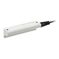
3 Names of Individual parts
3.1 D-MP#
3.2 Operation Display
Operation Light Colours
Category
Mode
Indicator
light 2
Indicator
light 1
Description
System
status
Analogue
Current
B
Analogue current
output active
Analogue
Voltage
G
Analogue voltage
output active
IO-Link
G
IO-Link connection
Error
O Sensor not ready for
operation /
Detectable magnetic
field is decrease.
LED flashing at 4 Hz
Switch
output
High
B Switch output High
Low
B Switch output Low
Over current
error
B Overload of the switch
output (over current)
Magnetic
field
In measuring
range
O Magnetic field
registered in
measuring range
Outside of
measuring
O Magnetic field is not
registered in
= LED ON, = LED flashing, = LED OFF
B = Blue, O = Orange, G = Green
4 Installation
4.1 Installation
Warning
• Do not install the product unless the safety instructions have been read
and understood.
• Use the product within the specified operating pressure and
temperature range.
• When mounting an actuator position sensor, use a mounting bracket
appropriate for the cylinder/actuator.
• The mounting method differs according to the type of actuator and the
inner diameter of the tube.
• When mounting a sensor for the first time, check that the
cylinder/actuator has a built-in magnet and use an appropriate bracket
for the cylinder/actuator. There are also cases when a bracket is not
needed.
• Use the correct tightening torque
When tightening mounting screws, use a suitable hexagon wrench
(size 1.5). Recommended torque should be 0.2 to 0.4 Nm.
Over-tightening can damage the cylinder/actuator and sensor.
Loose screws can cause misalignment or a reduction in accuracy
during operation. Tightening below the specified tightening torque will
allow the position sensor to move out of position.
• Do not carry an actuator by the position sensor lead wire.
• This may cause a broken lead wires or damage to the auto switch
internal elements.
• Use only the screws installed in the position sensor body for mounting
the position sensor.
If other screws are used, the position sensor may be damaged.
• Check and adjust the actual product operation during installation.
The auto switch may not operate in the correct actuator mounting
position due to the installation environment. Also check and adjust the
auto switch operation when used in intermediate stroke positions,
according to the operating environment.
• Press the switch down into the cylinder/actuator switch mounting
groove as shown.
• Tighten the mounting screws evenly.
4.2 Environment
Warning
• Do not use in an environment where corrosive gases, condensation,
chemicals, salt water or steam are present.
• Do not use in an explosive atmosphere.
• Do not expose to direct sunlight. Use a suitable protective cover.
• Do not install in a location subject to vibration or impact in excess of
the product’s specifications.
• Do not mount in a location exposed to radiant heat that would result in
temperatures in excess of the product’s specifications.
• Do not use in a location where magnetic fields are generated.
Orange
Green
Blue Blue
Refer to Declaration of
Conformity for relevant
Model
D-MP
025∗
D-MP
050∗
D-MP
100∗
D-MP
200∗
Length determination
25 mm
50 mm
100 mm
200 mm
Power supply voltage
15 to 30 VDC, ripple (p-p) 10% or below
(with power supply polarity protection)
(when no load is applied)
o
Resolution 0.05 mm
Linearity ±0.3 mm (@25
o
C)
Switch
output
NPN or PNP 1 output (push-pull)
Max. load
40 mA
Internal
voltage
2 V or less
Leakage
current
NPN: 0.5 mA or less at load resistance 3 kΩ,
1.5 mA or less at load resistance 750 Ω
Short
circuit
Yes
Analogue
current
output
Output
4 to 20 mA
Max. load
500 Ω
Analogue
voltage
output
Output
0 to 10 V
Min. load
resistance
2 kΩ
PUR 4 core φ2.6 0.08 mm
2
2
50 MΩ or more with 500 VDC Ohmmeter
Withstand voltage 1000 VAC 1 minute
Ambient temperature -10 to 60
o
C
Lead wire
Mounting screw
Operation display
Mounting screw
Teach pad