D-MP-SMX03EN
Page 2 of 3
4 Installation (continued)
4.3 Wiring
Caution
• Do not perform wiring while the power is on.
• Confirm proper insulation of wiring.
Check that there is no faulty wiring insulation (short circuits, faulty
ground connections, improper insulation between terminals, etc.), as
this may damage the auto switch due to over current.
• Do not route the auto switch wiring in the same place as power cables
or high voltage cables.
Otherwise auto switch malfunction may result due to noise and inrush
current.
• Avoid repeatedly bending or stretching the lead wire.
Broken lead wires will result if bending stresses or tensile forces are
applied to the lead wires.
Stress and tensile forces applied to the connection between the lead
wire and the product increases the possibility of disconnection.
Secure the lead wire to reduce any movement in the area where the
lead wire connects with the position sensor.
• Do not allow short-circuit of loads.
There is a risk of damage of position sensor.
• Keep wiring as short as possible to prevent interference from
electromagnetic noise and surge voltage. Do not use a cable longer
than 20 m.
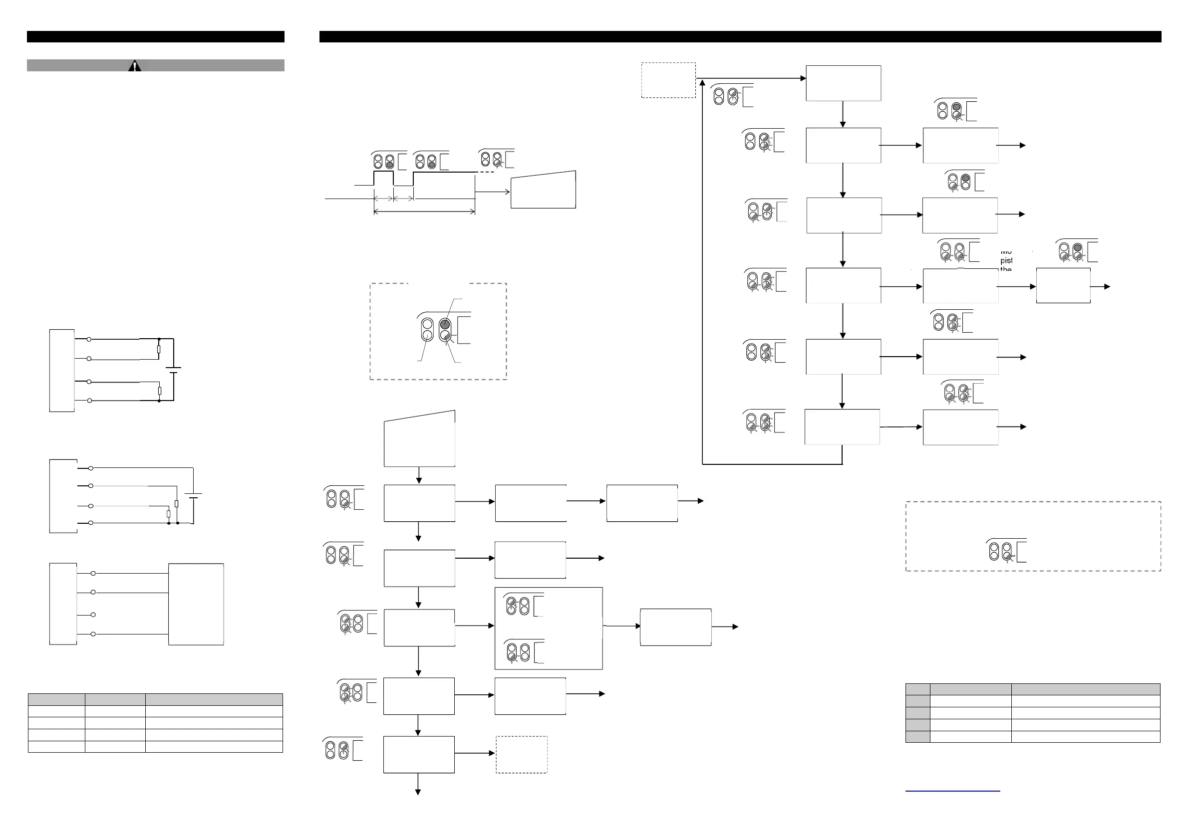
4.4 Wiring Diagram
SIO mode - NPN output
SIO mode - PNP output
IO-Link mode
• Analogue output (white) is disabled when IO-Link mode is selected.
4.5 Connector pin layout
Pin number Wire colour Description
1 Brown Power supply DC (+)
2 White Analogue current / voltage output
3 Blue Power supply DC (-)
4 Black IO-Link / Switch output (C/Q)
5 Setting
5.1 Initial settings
Switch output: Low (NPN = ON, PNP = OFF),
Analogue output: Current output, Range: Full range
• Teach pad setting procedure
NOTE: For teaching the measurement range, make sure that the piston
position is at the start point of the range.
Click the teach pad, and then click and hold down the teach pad.
• Teach Level 1 starts when the indicator LED flashes slowly.
NOTE: If the indicator LED does not flash and setting is not available,
wait for 3 seconds and double-click the teach pad again.
5.2 Teach Level 1
5.3 Teach Level 2
5.4 Setting completed
5.5 IO-Link parameter settings
• IODD file
IODD (I/O Device Description) is a definition file which provides all
properties and parameters required for establishing functions and
communication of the device.
IODD includes the main IODD file and a set of image files such as vendor
logo, device picture and device icon.
The IODD file is shown below.
Product No.
IODD file
∗
1 D-MP025A/B/C SMC-D-MP025-yyyymmdd-IODD1.1
2 D-MP050A/B/C SMC-D-MP050-yyyymmdd-IODD1.1
3 D-MP100A/B/C SMC-D-MP100-yyyymmdd-IODD1.1
4 D-MP200A/B/C SMC-D-MP200-yyyymmdd-IODD1.1
∗: "yyyymmdd" indicates the file preparation date. yyyy year, mm month
and dd day.
The IODD file can be downloaded from the SMC website (URL:
https://www.smcworld.com)
Power supply
15 to 30 VDC
Brown (1)
Black (4)
White (2)
Blue (3)
Main circuit
Brown (1)
Black (4)
White (2)
Blue (3)
Main circuit
Power supply
15 to 30 VDC
Black (4) C/Q
IO-Link
master
Click, then click
and hold down
the teach pad
Release
the pad
Complete
2 [Hz]
2 s or more
Complete
4 [Hz]
5 s or more
2 [Hz]
2 [Hz]
Current output
mode
for 2 s or
longer
Click the teach pad
to change
Move the
piston,
then click
the pad
Release
Voltage output
mode
8 s or more
4 [Hz]
4 [Hz]
Teaching of the
measurement
range
Measurement
range reset
Change the
analogue output
mode
Release
The start point
is selected
The end point
is selected
Release
Measurement
range reset
completed
Reverse
analogue output
Complete
Complete
11 s or more
Release
2 [Hz]
Teach
Level 2
15 s or more
Complete
The analogue
output mode is
Analogue output
reverse
completed
Switch output
mode
2 [Hz]
Teach Level 1
2 [s]
LED ON
LED
LED
flashing
Display
Teach
Level 2
Complete
Complete
2 [Hz]
2 [Hz]
2 [Hz]
2 [Hz]
2 [Hz]
2 [Hz]
2 [Hz]
4 [Hz]
2 [Hz]
4 [Hz]
4 [Hz]
2 [Hz]
1 [s]
1 [s]
4 [Hz]
1 [s]
1 [s]
2 [Hz]
Click and hold
the teach pad
3 s or more
6 s or more
9 s or more
12 s or more
Release
the pad
Release
the pad
Release
the pad
Move the
piston,
then click
the pad
Single switch point
mode
Window mode
Switch point
reset
Single switch point
setting
Switch point
setting
Start point
setting
End point
setting
Reverse switch
output
Reset
completed
Reverse
completed
Complete
Complete
Auto switch
mode
Release
the pad
Complete
Release
the pad
15 s or more
1 [s]
2 [Hz]
2 [Hz]
1 [s]
1 [s]
1 [s]
When a magnet (subject to be detected) is present outside of the
measurement range, the indicator LED flashes 4 times and setting
is complete.
4 [Hz]
 Loading...