Tallinn Science Park Tehnopol,
Akadeemia tee 21/6, Tallinn 12618, Estonia
Phone: + 372 6559914,
e-mail: sale@smd.ee
url: http://smd.ee
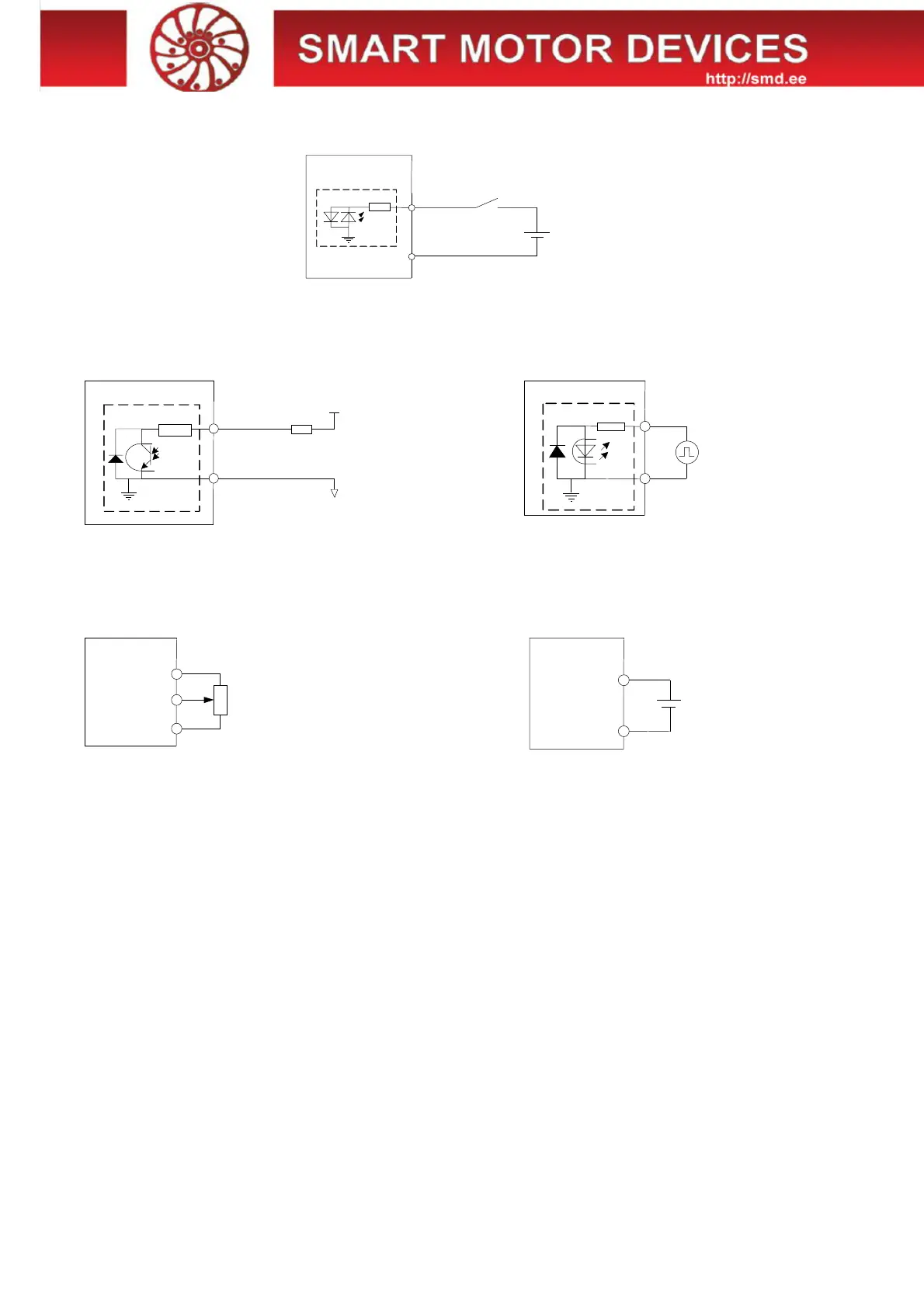
Connection examples for control inputs and outputs of the driver:
Fig.3. Connection of the input signals (4...12VDC) to an external controller.
*
It is possible to use the voltage 24VDC as a high level signals for inputs DIR and ENABLE on condition of using additional current
limiting resistors 1kOhm.
Fig.4. An example of output signal FAULT connection.
Signal type – opto-coupler output. Max. voltage: 48VDC, max.
current: 50 mA
Fig.5. An example of input STEP connection, high
level voltage signal 4…12VDC (24VDC
*
). It is
possible to use the voltage 24VDC as a high level
signals for input STEP on condition of using
additional current limiting resistors 3kOhm.
Fig.6. Analog speed control or analog position control with the
use of an external potentiometer
Fig.7. Analog speed control or analog position control
with the use of an analog voltage signal 0…5VDC
source.
Connection of an external braking resistor
Braking (regenerative) resistor is meant to be used to absorb and dissipate energy, which appears due to deceleration or forced
rotation of the motor (as an example, during deceleration of a high inertia load). The driver is equipped with an internal regenerative
resistor for 5W. The power of the resistor is suitable for normal operation of a stepper motor SM8680.
In case of forced motor rotation at a speed below 120rpm (10 seconds average value at the desired interval from 0 to infinite), using
of an external regenerative resistor is not necessary.
In case of forced motor rotation at a speed 120...240 rpm (10 seconds average value at the desired interval from 0 to infinite), it is
necessary to connect an external brake regenerative resistor R=5 Ohm P=100W. The load resistor should be connected to the screw
terminals «GND» and «RES BRAKE» (fig.1).
Long duration forced motor rotation at average velocity more than 240 rpm (10 seconds average value at the desired interval from 0
to infinite) is forbidden.
Connection of a stepper motor
The driver provides operation with 2 or 4-phase stepper motors, 4, 6 or 8 wires. Winding connection examples are in the table 2. Connect
stepper motor wires to A+, A-, B+ and B- terminals of the driver according to the table 2.
COM
4...12VDC (24VDC
)
GND
1
kOhm
COM
100 Ohm
0VDC
R
+20VDC
FAULT
GND
COM
Driver
GND
STEP
3 kOhm
+5
Driver
GND (G)
SP (S)
R=3...4 kOhm
Driver
GND (G)
SP (S)
0...+5VDC
 Loading...