Tallinn Science Park Tehnopol,
Akadeemia tee 21/6, Tallinn 12618, Estonia
Phone: + 372 6559914,
e-mail: sale@smd.ee
url: http://smd.ee
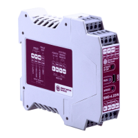
Table 2.
Scheme 1 Scheme 2 Scheme 3 Scheme 4
8 wires stepmotor connection (4 phases):
Scheme 1 – serial connection;
Scheme 2 – parallel connection.
6 wires stepmotor connection (2 phases with midpoint taps):
Scheme 3;
4 wires stepmotor connection (2 phases without midpoint taps):
Scheme 4.
Connection and assembling
Assembling order is as below:
1. Connect the driver to a stepper motor and power supply unit according the given schemes and recommendations;
2. If necessary, connect an external regenerative resistor.
6. Controller parameters settings
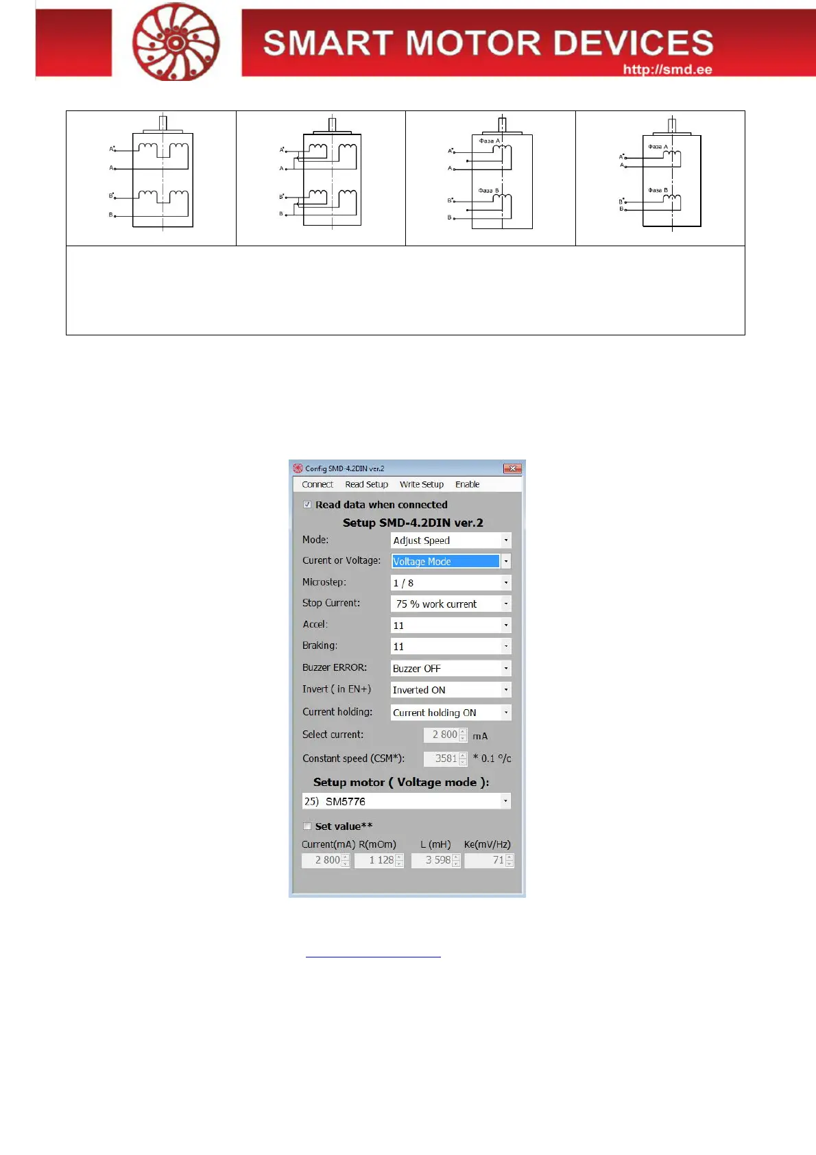
It is needed to connect the controller SMD-4.2DIN ver.2 via USB to a computer with windows OS to set the necessary control
parameters. For the purposes of the driver adjusting the special software is used.
Fig.8 Software for motor control parameters setting
6.1. Setting of parameters
· Download the software from web site https://smd.ee/software.htm
· Connect the controller SMD-4.2DIN ver.2 to the computer using a USB cable. It is not necessary to connect the controller to a
power supply unit – USB connection is enough for parameters setting.
· Check the COM port number from device manager of windows OS. This number should be in range from 1 to 9. If the number
differs, change it to any number from 1 to 9 (device manager - > port properties - > additional - > COM port number).
· Launch the program “Config SMD-4.2DIN ver.2”.