5
CAUTION: Due to the fact that the sections are top
heavy, it is absolutely necessary that the back section
be supported in such a manner as to prevent its falling
and causing potential serious bodily injury while
preparing to add the next section. One such way would
be to insert a piece of 3" x 36" piping in the lower port.
NOTE: Some sections may need shims under support
feet to align with other sections.
Stand the back section in place with the feet on and in the
angle iron rails. Support the section as required to prevent it
from falling forward or rearward. Clean hydronic gasket
recesses and rope groove with a stiff wire brush. Apply
spray-on adhesive (supplied with the boiler) to rope groove
to hold wicking in place during assembly.
CAUTION: Do not spray adhesive into the hydronic seal
ports.
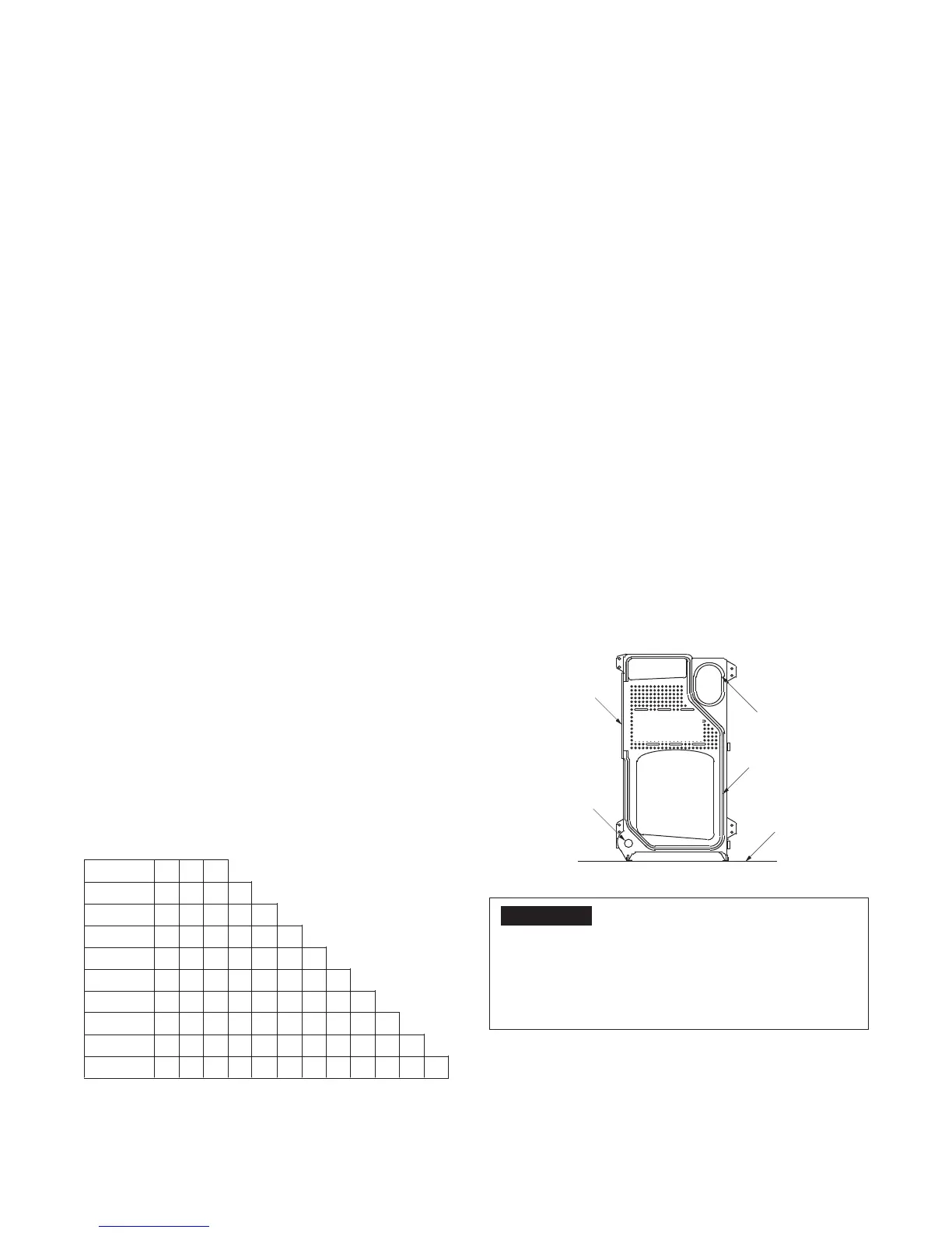
Apply a length of wicking avoiding bends and twists. Be sure
ends extend past the cleanout cover opening. (See Figure 2)
Place the upper and lower hydronic seals in the recessed
section taking care not to dislodge the rope or the hydronic
seals. Inspect the alignment of the sections through the open
ports and, if properly aligned, install the draw rods with nuts
drawn hand-tight. (See Figure 3) Plumb the sections before
applying torque to the upper right and lower left draw rods.
Maintain fi nger-tight torque on upper left and lower right draw
rods.
Figure 2
IMPORTANT
The upper and lower ports should be drawn up metal to
metal around the outside of the hydronic seal. Metal to
metal conditions will not occur at any other location.
Avoid excessive torque on upper left and lower right draw
rods, which may warp the section. See Figure 3 for correct
alignment of the seal.
Assemble additional sections as described above.
After draw rods are hand tight, torque as shown in Table 3.
5. COMBUSTION AND VENTILATION AIR
An adequate supply of air for the boiler room must be provided
to allow complete combustion of fuel and ventilation of the
room to avoid excessively high ambient temperature. Air inlet
by natural ventilation directly from the outside shall have
total free area of not less than one sq. in. per 14,000 BTU
per hour of input of all fuel burning appliances in the boiler
room.
CAUTION: Never use an exhaust fan in the boiler room.
The boiler room must never be under negative a pressure
or improper burner operation will occur!
Where combustion air must be obtained through ducts, see
ANSI/NFPA 31 or ANSI Z223.1 for requirements.
If mechanical combustion air supply is required, the system
must be approved by the local authorities, and should provide
at least 30 CFM per gallon of oil and .35 CFM/1,000 BTU HR
(.034 m
3
/min per kw) of gas input to the boilers.
Ventilation air, if required, must be in addition to the
combustion air quantities called for above.
6. ASSEMBLY OF SECTIONS
When boilers are delivered to the job site, each item should
be inspected closely for possible shipping damage. Scars or
nicks in the port sealing surfaces may allow leakage. Do not
attempt to use any section that has been damaged in the
port seal area.
When ready to commence assembly, recommended on a level
pad, place the angle rails in position parallel with each other
with the 2" legs on the fl oor and measuring 25-21/32 inches
outside dimension. Be sure to align the center of the boiler
with the center line of the pad. If no pad is provided, shim and
grout under the angles to make them level and provide support
along the full length. (See Figure 1) Clean hydronic gasket
recesses and rope groove with a wire brush, taking care not
to damage machine surface.
See Table 2 for proper location of sections.
Table 2 - Section Locations
F = Front Section
P = Plain intermediate section
H = Heater intermediate section-Optional, must be ordered.
B = Back Section
SERIES 19HE BOILER
INSTALLATION INSTRUCTIONS
3 SECT
4 SECT
5 SECT
6 SECT
7 SECT
8 SECT
9 SECT
10 SECT
11 SECT
12 SECT
F
F
F
F
F
F
F
F
F
F
H
P
H
P
H
P
P
P
P
P
B
H
P
H
P
H
H
P
P
P
B
H
P
H
P
P
H
P
P
B
H
P
H
H
P
H
P
B
H
P
P
H
P
H
B
H
H
P
H
P
B
P
H
P
H
B
P
H
P
B
P
H
B
P
B
HEATING
SURFACE
CLEANOUT COVER
LOWER PORT
UPPER PORT
CERAMIC ROPE
JOINT SEAL
FLOOR
SECTIONAL VIEW