EasyManua.ls Logo

Smoby 721007 User Manual

Smoby 721007
9 pages
To Next Page IconTo Next Page
Page #1 background imageLoading...
Page #1 background image
A
B
x1
x1
x3
x1
x1
x1
x1
x1
x1
x2
x1
x1
x1
C
D
E
X1
12
9
3
6
F
G
R
S
T
V
W
M
J
L
N
P
Q
0h45
x1
x1
x1
x1
x4
BB
BC
BD
BE
BF
BA
O 6x30 mm
O 8x200 mm
O 6x14 mm
O 8x124mm
AAK0368
AAK0444
AAK0445
9160010
9180147
x3
O 4,5x20 mm
AAK0401
I15006
I15019
H
K
I18008
I18009
I18014
I15014 I18013
I15013
I18012
I18010
ABA1340
ABA1338
I18011
TOOL ONLY
SERT COMME OUTIL
18
FR •ATTENTION!
GB •WARNING!
DE •ACHTUNG!
NL •WAARSCHUWING!
ES •¡ADVERTENCIA!
PT •ATENÇÃO!
IT •AVVERTENZA!
DK •ADVARSEL!
SE •VARNING!
FI •VAROITUS!
NO •ADVARSEL!
HU •FIGYELMEZTETES!
CZ •UPOZORNĚNÍ!
SK •UPOZORNENIE!
AR
PL •OSTRZEŻENIE!
BG •ВНИМАНИЕ!
RO •AVERTISMENT!
GR •ΠΡΟΕΙΔΟΠΟΊΗΣΗ!
SI •OPOZORILO!
HR •UPOZORENJE!
TR •UYARI!
RU •ВНИМАНИЕ!
UA •УВАГА!
EE •HOIATUS
LT •DĖMESIO!
LV •UZMANĪBU!
mois
months
Monate
maanden
meses
meses
mesi
måneder
månader
mesecev
mjeseci
ayda
месяцев
місяців
kuud
mėn
mēneši
kuukauden
måneder
hónapban
měsíců
mesiacov
miesięcy
месеца
luni
μηνών
AAP2336B P1/9
Question and Answer IconNeed help?

Do you have a question about the Smoby 721007 and is the answer not in the manual?

Smoby 721007 Specifications

General IconGeneral
BrandSmoby
Model721007
CategoryToy
LanguageEnglish

Summary

Parts Identification

Major Components Identification

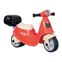
Visual identification of major scooter components labeled A through W.

Hardware and Fasteners List

List of screws, bolts, and washers with their dimensions and part numbers.

Safety and Customer Information

Customer Service and Warranty Information

Contact details and after-sales service information for Smoby Toys.

Essential Safety Warnings

Warnings regarding adult supervision and assembly by an adult.

Assembly Instructions - Steps 1-2

Step 1: Wheel Assembly

Instructions for assembling the wheels (E, Q) onto the scooter base.

Step 2: Handlebar Post Attachment

Attaching the handlebar post (BA) to the scooter base using screws (BD, T).

Assembly Instructions - Steps 3-4

Step 3: Rear Wheel and Brake Assembly

Assembling the rear wheel (E) and brake components (P, BF, M, N).

Step 4: Steering Mechanism Assembly

Connecting steering components (G, F, H) using screws (T, BD).

Assembly Instructions - Steps 5-6

Step 5: Front Fork and Rear Axle Attachment

Attaching the front fork (A) and rear axle assembly (C, D).

Step 6: Axle and Wheel Mechanism Assembly

Assembling the axle components (K, L, J) and rear wheel mechanism (R).

Assembly Instructions - Steps 7-8

Step 7: Handlebar Assembly

Assembling the handlebars using screws (BC, BF).

Step 8: Handlebar Cover Attachment

Attaching the cover (W) to the handlebar assembly.

Assembly Instructions - Steps 9-14

Step 9 & 10: Seat and Wheel Integration

Attaching the seat (B) and final wheel components (S).

Steps 11-14: Accessory and Storage Attachment

Mounting fenders (AA) and storage compartments (AB, AC, Y, Z).

Related product manuals