Page 3-14
CHAPTER 3 CHECKOUT, CALIBRATION AND MAINTENANCE
Effective
09/2005
BRAKE SOLENOID
• Disconnect the power from the rear of the
machine.
• Remove the Display panel
• Remove the weight tray.
• Disconnect wiring harness from the brake
solenoid.
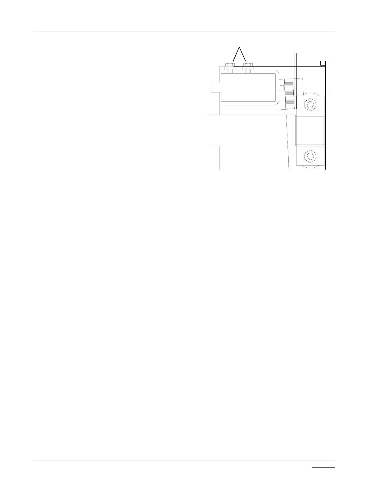
• Remove the two #2 phillip screws. (Figure 3-20)
• Reverse procedures for installation.
BRAKE SOLENOID ADJUSTMENT
• Loosen the two phillip screws holding the brake
pad and arm and move towards the brake band.
The gap between the brake pad and brake band
is 1/16”. Tighten the two screws holding the
brake arm.
• Loosen the two phillip screws holding the brake
solenoid in place.
• Slide the brake solenoid towards the brake pad
until the solenoid plunger makes contact with
the back of the brake pad, maintaining the 1/16
between the brake pad and the brake band.
• Tighten the two screws holding the solenoid and
test the brake.
SHAFT BRAKE BAND
• Disconnect power.
• Remove Main PCB.
• Remove weight tray.
• Using a 1/2” socket remove the two self
locking nuts and flat washers.
• Remove both brake bands.
• Apply a small amount of white lithium grease
between the shaft and band before installing.
• Using a 15” tire and wheel tighten bands to
where the tire and wheel assembly will stop
after 1 1/2 to 2 revolutions after the brake
kicks in.
1/16”
Figure 3-20
ÎÍ
Phillip screws
 Loading...