www.snapper.com22
Maintenance
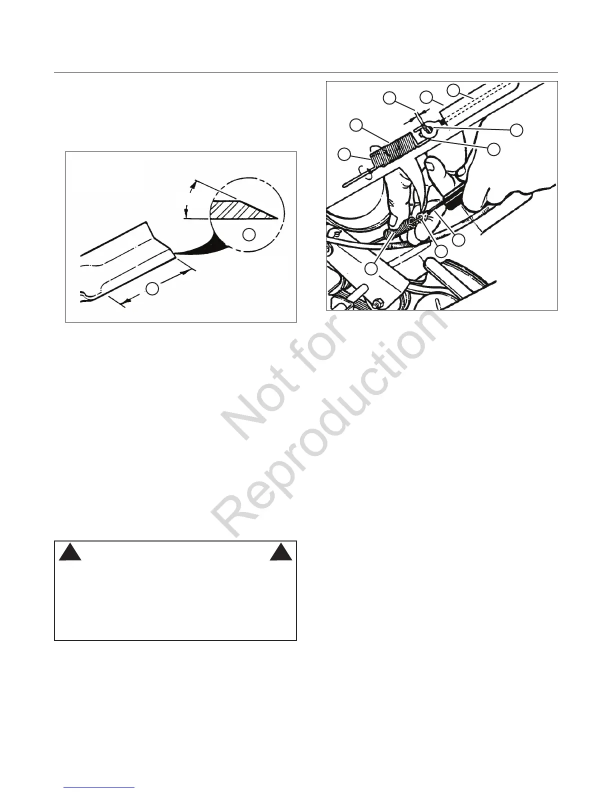
Blade Sharpening (Continued)
4. Sharpen the blade on a grinding wheel at an angle
of 22 to 28 degrees (B, Figure 21). DO NOT
sharpen the blade beyond the original cutting edge
(A).
Do not sharpen
beyond original
cutting edge
End view of
blade assembly
22-28
0
Figure 21: Sharpening the mower blade
A
B
5. Check blade for balance. If necessary, correct bal-
ance by grinding heavy end of blade.
6. Reinstall blade (B, Figure 20). Note the correct
assembly order:
(A) Blade hub
(B) Blade
(C) Blade flange (facing up)
(D) Cone washer (concave side up)
(E) Capscrew
7. Check torque of blade retaining cap screw.
Recommended torque should be 40 lb-ft (54 N.m).
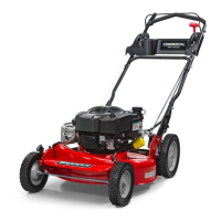
Wheel Drive Control
Adjustment
WARNING
DO NOT attempt any maintenance, adjustments or
service with engine and blade running. STOP engine
and blade. Disconnect spark plug wire and secure
away from spark plug. Engine and components are
HOT. Avoid serious burns, allow sufficient time for all
components to cool.
! !
1. The wheel drive control is properly adjusted when
there is 1/16” to 1/8” clearance (G, Figure 22)
between the inside of the spring hook (E) and the
inside of the clutch cable eye (C) with the wheel
drive control released.
Figure 22: Wheel drive control adjustment
D
B
A
G
F
C
E
A
D
C
2. To adjust, unhook the upper spring (D) from the
cable eye and rotate the spring in the direction
required to extend or shorten the spring length.
3. Rehook the upper spring to the cable eye and
check clearance. Repeat the procedure if required.
NOTE: The vinyl spring cover (B) should be kept over
the spring at all times except for adjustments.
4. If the wheel drive control fails to return quickly to
the “OFF” position when released, check for bind-
ing at the cable holdings located on the side of
the right handle. The upper clip should be located
2” below the upper knob; the lower clip should be
4” above the lower knob. The cable should slide
freely with the clips installed at these locations.