ASSEMBLY
7
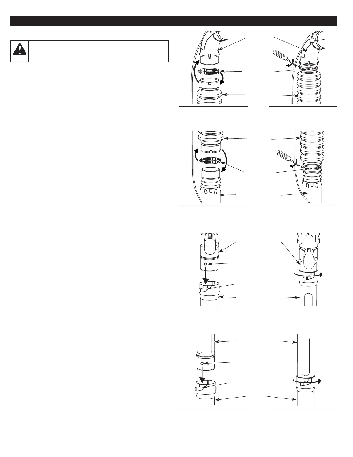
ASSEMBLING THE BLOWER TUBE
Installing the Flex Tube
1. Place a hose clamp around one end of the flex tube (Fig. 1).
2. Slide the flex tube and hose clamp onto the elbow tube (Fig. 1).
3. Tighten the screw on the hose clamp with a flat-head
screwdriver (Fig. 1).
Installing the Upper Blower Tube
1. Place a hose clamp around the other end of the flex tube (Fig. 2).
2. Slide the flex tube and hose clamp onto the upper end of the
upper blower tube (Fig. 2).
3. Tighten the screw on the hose clamp with a flat-head
screwdriver (Fig. 2).
Installing the Lower Blower Tube
1. Align the bump on the upper blower tube with the bump slot on
the lower blower tube (Fig. 3).
2. Insert the upper blower tube into the lower blower tube (Fig. 3).
3. While holding the upper blower tube, twist the lower blower tube
clockwise until it locks into place (Fig. 3).
Installing the Nozzle
1. Align the bump on the lower blower tube with the bump slot on
the nozzle (Fig. 4).
2. Insert the lower blower tube into the nozzle (Fig. 4).
3. While holding the lower blower tube, twist the nozzle clockwise
until it locks into place (Fig. 4).
Fig. 1
Hose Clamp
Flex Tube
Elbow Tube
Fig. 2
Fig. 3
Upper Blower Tube
Lower Blower Tube
Bump
Bump Slot
Fig. 4
WARNING:
To avoid serious personal injury and
damage to the unit, shut the unit off before removing or
installing blower tubes or nozzles.
Flex Tube
Hose Clamp
Upper Blower Tube
Lower Blower Tube
Bump
Bump Slot
Nozzle