EN
In designing and manufacturing the various Series of the manufacturer's Fans and Extractors, Hazard Elimination has been
taken into account, in order to meet the conditions for Integrated Safety.
When their configuration and manufacturing processes permit this, the manufacturer directly incorporates the most appropriate
Safety Devices. If the conditions for installation or use mean that these devices cannot be incorporated at source, all additional
safety accessories are available for implementation when the equipment is installed and before it comes into service.
6. Installation and Assembly
This equipment may only be installed by a qualified technician who is familiar with the installation, monitoring and maintenance
of this type of equipment, and uses suitable tools.
Mechanical
• To ensure safe operation, the equipment must be firmly fixed.
• The installation must prevent contact with the fan's impeller, through the use of grilles, accessories, or by installing a
connecting tube of a suitable length.
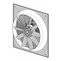
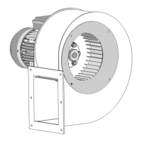
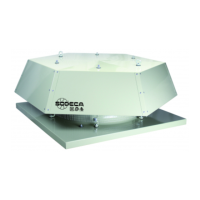
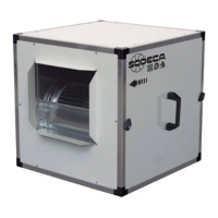
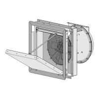
• The equipment may be installed in different ways, depending on each need. (Fig. 1)
• Do not connect the elbows close to the equipment's connecting flanges or clamps.
•
Leave sufficient room to be able to open the control panel door.
• The equipment must be installed in such a way that the whole of its surface area is stuck to the surface on which it is
installed.
• The installation must be such that the weight of the system of ducts is not supported by the equipment.
• When connecting the ducts, ensure that the direction of airflow is correct in accordance with the arrows indicating flow
direction through the equipment.
• The external control panel must be installed in the access inside the area to be pressurised.
• The air connection must be executed with a 4mm diameter tube, and it must be located at the end of each tube in the
following position or zone:
o (+) Leave the tube in the zone to be pressurised in the event of a fire.
o (-) Leave the tube in the benchmark pressure zone. Protect it to prevent contact with water.
• Once the mechanical assembly is complete, it is important to check that the impeller turns freely, with no friction or
tension
Electrical
• Make sure the equipment is connected to a power supply as per the instructions with the connection diagram at the
beginning of this document (Fig. 7, 8, 12 and 13)
• For the electrical supply connection for this fan, special cable certified as compliant with fire regulations must be used,
of a suitable cross-section for the current the fan uses.
• IMPORTANT: When the equipment is controlled by reducing the voltage, the motor's current may be higher than the
rated value.
• Check that the electrical characteristics stated on the plate correspond to the power supply.
• The equipment's earth connection must be connected.
Start-up
• After installing the equipment, check that there are no alarm signals in the box BOXPDS (Fig. 5) inside the control
panel. If this is not the case, turn one of the power input phases to ensure the equipment functions correctly.
• After starting up the motor, it is important to check that the motor is turning correctly, without vibrations, and is not
making unusual noises.
• A check must be made to ensure that the motor's actual power consumption does not exceed the level stated on the
equipment's label and that it does not heat up excessively.
IMPORTANT:
This operation must only be performed by the authorised installer or the manufacturer.
Before start-up, check the correct operation of the equipment in the case of fire. To do this, first verify that there are no failure pilot
lamps lit on the control panel. Once this has been done, activate the manual selector switch, after first closing the doors of the area
that is to be pressurised. The next step is to check that the necessary 50Pa in the pressurised area have been reached, and then
configure the Safety Speed parameter, with the frequency value indicated by the Frequency Converter (VSD1) for pressurisation
at 50Pa.
After verifying the correct operation of the equipment, change the position of the selector switch from Manual to Automatic to start
up the equipment.
 Loading...