Setting up the Reader
10
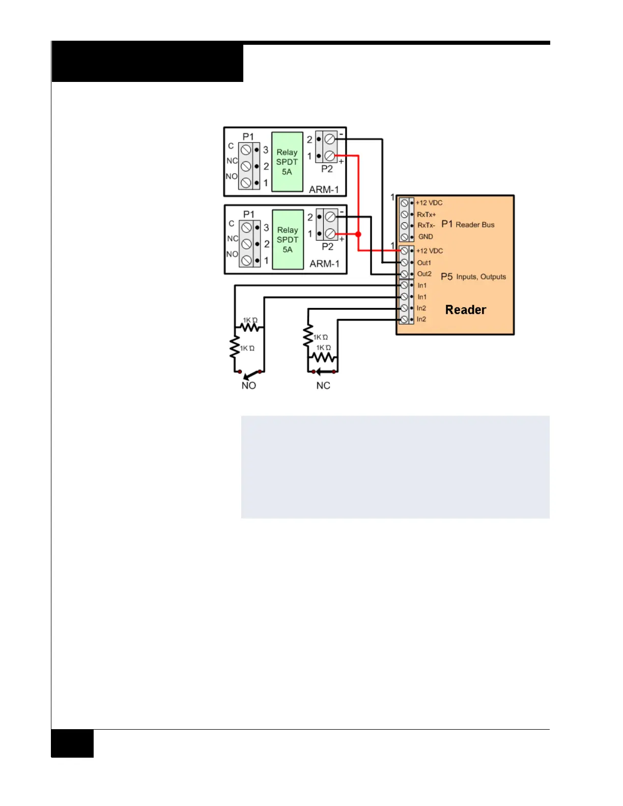
Figure 6. RM-4 Input/Output Connections
Installing the ARM-1 Relay Module
Two ARM-1 relay components can be connected to the RM reader through the
P5 connector (Table 4 on page 11).
RM P5-1 is the common (+12 VDC) pin for either ARM-1.
RM P5-2 is the output drive (GND) for the first relay.
RM P5-3 is the output drive (GND) for the second relay.
NOTE
The ARM-1 has not been evaluated by UL.
Maximum distance from P5 to the ARM-1 is 25 feet.
Maximum distance from P5 to the inputs is 2000 feet.
Locate the 1Kresistors for the NO and NC supervised inputs as close as
possible to the switch.
To comply with UL requirements, use shielded, minimum 22 AWG stranded,
twisted pair cable.