9
Solar-Log™ PRO380 Mod
Solar-Log™ PRO380 Mod
4 Solar-Log™ PRO380 Mod
4.1 Solar-Log™ PRO380 Mod
Selections available under Solar-Log Pro
Overview
•
The communication address has to be assigned.
•
2-pin wiring
•
Installation steps
• Switch off the meter and the Solar-Log™.
• Connect the meter to the Solar-Log™.
Note
The communication address is set to 1 by default, but can be adjusted if several meters are
connected to one RS485 bus. Maximum of 32 meters per RS485 bus
Connect the meter to the Solar-Log™.
The wiring is done using a
•
self-made cable connection with a terminal block connector.
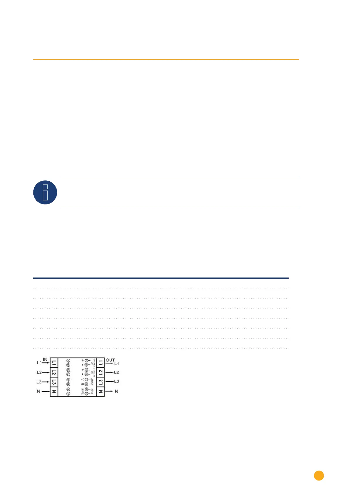
4.1.1 Connection diagram
according to circuit type 1000 (DIN 43856)
Input "L1, L2, L3" Supply line input phase "L1, L2, L3"
Output "L1, L2, L3"
Supply line output phase "L1, L2, L3"
Terminal "N" Neutral conductor connection "N"
Terminal 18, 19 S
o
pulse output "consumption" (terminal 18 = "+")
Terminal 20, 21 S
o
pulse output "supply" (terminal 20 = "+")
Terminal 22, 23 ModBus connection terminal 22 -> A, 23 -> B
Terminal 24, 25 External tariff switching (230V AC)
The SO signal for the supply is not used when a meter
is connected to the Solar-Log™.
 Loading...