Do you have a question about the Solar 4001 and is the answer not in the manual?
Use manufacturer-recommended attachments. Disconnect by plug, not cord. Ensure cord placement is safe.
Do not operate with damaged cords/plugs. Do not disassemble the control cabinet; seek qualified service.
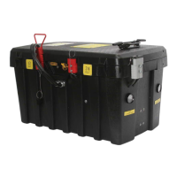
Unplug unit before maintenance. Ensure all vents on the Battery Tray Assembly remain unobstructed.
Have assistance and supplies ready. Avoid sparks, flames, and metal objects near batteries.
Handle acid spills promptly. Remove metal jewelry. Charge only lead-acid batteries; never frozen ones.
Unit requires grounding via a 120VAC cord and properly installed outlet; do not alter cord/plug.
Overview of the front panel with indicators for jump starting and recharging.
Status lights for connection, boost mode, voltage errors, and reverse polarity.
Status lights indicating charging progress and completion.
Master On/Off Switch, Battery Type Setting, Battery Status Display, and Boost Mode Timer.
12V, 24V, and Voltage Selection Quick Connects for configuring output and charging.
Red connector used to activate the Charging Mode.
Gray connectors for transferring power to the output cables and clamps.
Lists all components included with the unit and the tools required for assembly.
Specifies the recommended battery types and specifications for the unit.
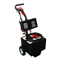
Step-by-step guide for the initial assembly of the unit.
Guide for attaching the handle and correctly installing the batteries.
Steps for wiring the unit to operate in 12V or 24V mode.
Instructions for mounting the gray output power connectors.
Detailed steps for connecting various cables to battery terminals.
Connects control wires to battery terminals based on color and label.
Secure battery terminals and connect output cables to the unit.
Mount bracket and set battery type and boost mode timer duration.
Set voltage, position cables, stay clear of moving parts, and connect clamps correctly.
Engage Boost Mode, handle voltage errors, and start the vehicle.
Disconnect clamps safely, adjust timer, and disconnect output cables.
Set battery type switch and connect power cord to unit and AC outlet.
CHARGING LED indicates progress. CHARGE COMPLETE LED indicates full charge.
Details on warranty period, exclusions, and limitations for the jump starter.
Information on registering the purchase for service and product updates.
| Range | Up to 3000 feet |
|---|---|
| Remote Start | Yes |
| Keyless Entry | Yes |
| Security System | Yes |
| Battery Life | Up to 1 year |