Do you have a question about the Solar BA5 and is the answer not in the manual?
Steps to prepare a battery for testing, including ventilation and terminal cleaning.
Procedure for connecting the tester and performing a battery test using the device.
Steps for conducting starting and charging system tests on BA7 model.
Steps to follow for obtaining warranty service or exchanging the product.
Guidance on registering the product for updates and better service.
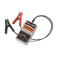
The SOLAR Battery Tester (Model BA5) and SOLAR Battery and System Tester (Model No. BA7) are diagnostic tools designed to assess the health and performance of 12-volt lead-acid batteries and, in the case of the BA7, the vehicle's starting and charging systems. These testers are compatible with a wide range of battery types, including Conventional, Maintenance Free, AGM, Gel Cell, Marine, and Deep Cycle batteries, making them versatile for various applications.
The primary function of these devices is to provide an accurate assessment of a battery's condition and, for the BA7, the overall health of a vehicle's electrical system. They achieve this by measuring key electrical parameters and comparing them against established rating systems.
For battery testing, the devices determine the battery's ability to hold a charge and its overall capacity. This is crucial for identifying weak or failing batteries before they cause issues. The testers can evaluate batteries against several common capacity rating systems, including CCA (Cold Cranking Amps), DIN, IEC, EN, and CA (Cranking Amps) or MCA (Marine Cranking Amps). This allows users to test batteries according to their specific manufacturer ratings.
The BA7 model extends its diagnostic capabilities to the vehicle's starting and charging systems. The starting system test assesses the starter's performance by measuring the minimum voltage reached by the battery during engine cranking. This helps identify issues with the starter motor, wiring, or connections. The charging system test evaluates the alternator and voltage regulator by measuring the charging system voltage both without loads and under various electrical loads (e.g., headlights, blower motor). This helps determine if the charging system is overcharging, undercharging, or functioning correctly.
The testers utilize an LED display to show numerical readings and provide an LED assessment (Green, Green/Yellow, Yellow/Red, Red) to indicate the condition of the battery or system being tested. This visual feedback makes it easy for users to quickly understand the diagnostic results.
The SOLAR Battery Testers are designed for straightforward operation, guiding the user through the testing process with clear prompts and instructions.
Preparation: Before any test, it is essential to ensure the area around the battery is well ventilated. Battery terminals should be clean; a wire brush may be used if necessary, taking care to prevent corrosion from contacting the eyes. Users must inspect the battery for any physical damage like cracks or broken cases, as a damaged battery should not be tested. For non-sealed Maintenance Free batteries, distilled water should be added to each cell to the manufacturer-specified level to purge excessive gas. All vehicle accessories must be turned off to prevent arcing and ensure the battery has a nominal 12-volt charge. If the battery needs to be removed from the vehicle for testing, the ground terminal should always be disconnected first.
Connection: To begin testing, the tester leads are connected to the battery. The red clamp is attached to the positive battery terminal first, followed by the black clamp to the negative battery terminal. It is recommended to connect directly to the battery terminals or posts whenever possible for the most accurate readings.
Troubleshooting: The manual provides detailed troubleshooting steps for common display messages such as "HI" (voltage over 15V), "Lo" (voltage under 7V), "Blank" (voltage too low to power tester or reverse connection), "----" (unstable voltage), and a lit "RED Check Connection LED" (improper 12V battery connection or poor contact). These steps guide users to verify battery voltage, connections, and charge status, or to apply a temporary load to stabilize readings.
The SOLAR Battery Testers are designed for durability and ease of use, with minimal user maintenance required.
General Care: The devices should be handled with care to prevent damage. If the tester receives a sharp blow or is otherwise damaged, it should be checked by a qualified service person.
Disassembly: Users are explicitly instructed not to disassemble the tester. Any internal issues or repairs should be handled by a qualified service professional to maintain the device's integrity and warranty.
Environmental Considerations: The testers should not be submerged in water and should not be operated in the presence of flammables like gasoline. The recommended operating ambient temperature range is 32°F to 122°F, ensuring reliable performance within typical workshop or outdoor conditions.
Safety Precautions: Maintenance extends to ensuring user safety. Always wear eye protection and appropriate protective clothing when working near lead-acid batteries. Have fresh water and soap readily available in case of acid contact. Avoid dropping metal tools onto the battery, which could cause sparks or short circuits. Remove personal metal items like rings or watches to prevent severe burns from short-circuit currents. These safety measures are crucial for preventing accidents and ensuring the longevity of both the user and the equipment.
By adhering to these usage and maintenance guidelines, users can ensure accurate diagnostics and extend the lifespan of their SOLAR Battery Tester.
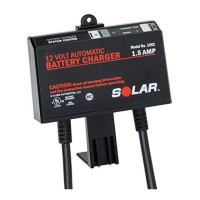
| Voltage | 12V |
|---|---|
| Amperage | 5A |
| Input Voltage | 100-240V AC |
| Output Voltage | 12V DC |
| Output Current | 5A |
| Compatibility | Lead-acid, AGM, Gel batteries |
| Protection Features | Reverse Polarity Protection, Overcharge Protection, Short Circuit Protection |