INCLINE &CONSOLE
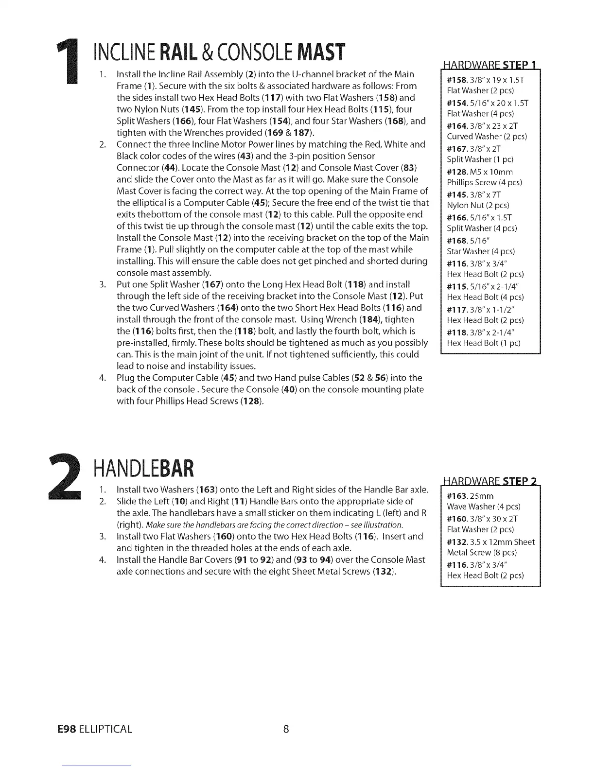
1. install the incline Rail Assembly (2) into the U-channel bracket of the Main
Frame (1). Secure with the six bolts & associated hardware as follows: From
the sides install two Hex Head Bolts (117) with two Flat Washers (158) and
two Nylon Nuts (145). From the top install four Hex Head Bolts (115), four
Split Washers (166), four Flat Washers (154), and four Star Washers (168), and
tighten with the Wrenches provided (169 & 187).
2. Connect the three Incline Motor Power lines by matching the Red, White and
Black color codes of the wires (43) and the 3-pin position Sensor
Connector (44). Locate the Console Mast (12) and Console Mast Cover (83)
and slide the Cover onto the Mast as far as it will go. Make sure the Console
Mast Cover is facing the correct way. At the top opening of the Main Frame of
the elliptical is a Computer Cable (45); Secure the free end of the twist tie that
exits thebottom of the console mast (12) to this cable. Pull the opposite end
of this twist tie up through the console mast (12) until the cable exits the top.
Install the Console Mast (12) into the receiving bracket on the top of the Main
Frame (1). Pull slightly on the computer cable at the top of the mast while
installing. This will ensure the cable does not get pinched and shorted during
console mast assembly.
3. Put one Split Washer (167) onto the Long Hex Head Bolt (118) and install
through the left side of the receiving bracket into the Console Mast (12). Put
the two Curved Washers (164) onto the two Short Hex Head Bolts (116) and
install through the front of the console mast. Using Wrench (184), tighten
the (116) bolts first, then the (118) bolt, and lastly the fourth bolt, which is
pre-installed, firmly. These bolts should be tightened as much as you possibly
can. This is the main joint of the unit. If not tightened sufficiently, this could
lead to noise and instability issues.
4. Plug the Computer Cable (45) and two Hand pulse Cables (52 & 56) into the
back of the console. Secure the Console (40) on the console mounting plate
with four Phillips Head Screws (128).
i
#158.3/8"x 19x 1.5T
FlatWasher (2 pcs)
#154.5/16"x 20 x 1.ST
FlatWasher (4 pcs)
#164.3/8"x 23 x 2T
Curved Washer (2 pcs)
#167.3/8"x 2T
Split Washer (1 pc)
#128. M5 x lOmm
Phillips Screw (4 pcs)
#145.3/8"x 7T
Nylon Nut (2 pcs)
#166.5/16"x 1.5T
Split Washer (4 pcs)
# 168.5/16"
StarWasher (4 pcs)
#116.3/8"x 3/4"
Hex Head Bolt (2 pcs)
#115.5/16"x2-1/4"
Hex Head Bolt (4 pcs)
#117.3/8"x 1-1/2"
Hex Head Bolt (2 pcs)
#118.3/8"x 2-1/4"
Hex Head Bolt (1 pc)
HANDLEBAR
1. Install two Washers (163) onto the Left and Right sides of the Handle Bar axle.
2. Slide the Left (10) and Right (11) Handle Bars onto the appropriate side of
the axle.The handlebars have a small sticker on them indicating L (left) and R
(rig ht). Make sure the handlebars are facing the correct direction - see illustration.
3. Install two Flat Washers (160) onto the two Hex Head Bolts (116). Insertand
and tighten in the threaded holes at the ends of each axle.
4. install the Handle Bar Covers (91 to 92) and (93 to 94) over the Console Mast
axle connections and secure with the eight Sheet Metal Screws (132).
#163.25mm
Wave Washer (4 pcs)
#160.3/8"x 30x 2T
FlatWasher (2 pcs)
#1:32.3.5 x 12rnm Sheet
Metal Screw (8 pcs)
#116.3/8"x 3/4"
Hex Head Bolt (2 pcs)
E98 ELLIPTICAL 8
 Loading...