/
ASSEMBLYINSTRUCTIONS
1.
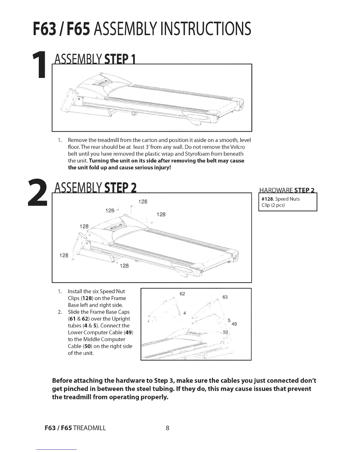
Remove the treadmill from the carton and position it aside on a smooth, level
floor.The rear should be at least 3'from any wall. Do not remove the Velcro
belt until you have removed the plastic wrap and Styrofoam from beneath
the unit. Turning the unit on its side after removing the belt may cause
the unit fold up and cause serious injury!
ASSF. LSTE
128
......
......... ,_,
128 :::: ........ .....
1:28
128
128
i
Clip (2 pcs)
1.
2.
Install the six Speed Nut
Clips (128) on the Frame
Base left and right side.
Slide the Frame Base Caps
(61 & 62) over the Upright
tubes (4 & 5). Connect the
Lower Computer Cable (49)
to the Middle Computer
Cable (50) on the right side
of the unit.
62
63
5
5O
49
Before attaching the hardware to Step 3, make sure the cables you just connected don't
get pinched in between the steel tubing. If they do, this may cause issues that prevent
the treadmill from operating properly.
F63 / F65 TREADMILL 8


 To Next Page