Visit solidremote.help if you need help
ALWAYS post a new topic in forum & double check email for prompt response, thanks.
--- Page
2
Basic Wiring Diagram
Wiring maybe complex depending on different applications, we just
included two simple diagrams below to explain the basic idea.
Basic electronics knowledge is required, customer
needs to make sure all parts in diagram meets our
specifications (for example, light bulb not exceeding 10A),
or it may cause unexpected results or damage.
Following examples are using 202U’s Relay 1 for
wiring, you can use Relay 2 of course, the idea is the same.
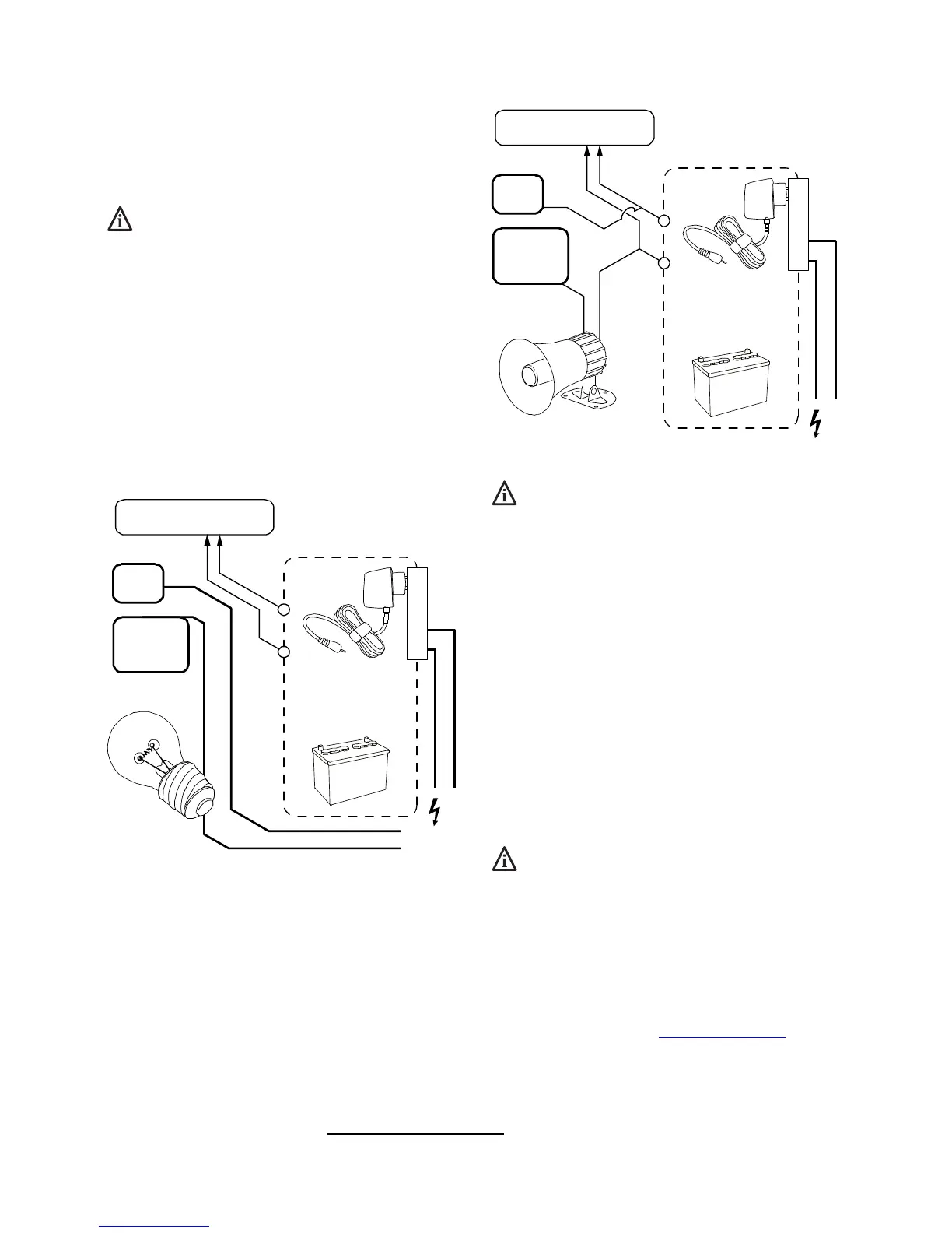
Basic wiring using separate power supplies
The following is a simple wiring diagram for controlling light bulb on
& off using our 202U receiver.
The light bulb is using 110Vac mains power, while our receiver is
using 12Vdc regulated power through power adapter or battery.
9-30V DC /
9-24V AC output
OR
110VAC
w/ DC jack to screw
terminals converter
202U’s power terminal
(polarity does not matter)
Relay 1
COM
Relay 1
NO*
Normally Open
NO terminal means normally open (disconnected to COM), and it will
close (connect to COM) when relay is activated (clicks).
When relay activates, NO is connected to COM internally through
onboard relay, circuit closed -> then light bulb should be turned on.
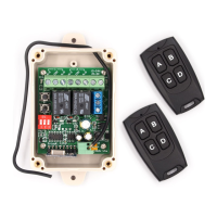
Basic wiring using the same power supply
When the target device also uses low power such as 12Vdc (for
example, the 12Vdc siren in diagram below), then our receiver can
share the same power supply with target device.
12V DC output
Due to siren req.
OR
110VAC
w/ DC jack to screw
terminals converter
202U’s power terminal
(polarity does not matter)
Relay 1
COM
Relay 1
NO*
Normally Open
Shared power source is not recommended for motor or
other electronics which introduce noise into power line.
Although 202U doesn’t care about polarity, your target
device may care, so inspect wiring carefully before power
up, to avoid damage.
Onboard Simple Limit Switches
LS on receiver board stands for limit switch, LS1 & LS2 controls
relay 1 & 2 respectively, they share a common connection COM, so
the 3 blue terminals from up to down can be read as LS1 COM LS2.
For example, when LS1 is connected to COM (by external limit
switch or other sensor outside), then relay 1 will be forced off, even if
remote control tells it to stay on.
Our limit switch is only for feedback control (to turn
relay off), NOT for direct manual override control!
Discover new features in V5 online!
There are many new features in V5 version
receiver, please check our full manual online.
It is available at solidremote.help
website,
the “SR-RCS-202U receiver manual” topic thread.
Thank you.