Anbqu
undWechsel
der
Schneidwerkzeuge
Molocense
so
legen,
doß die L,beits-
*elle
noch
oben
zeiot.
Achruno: Krofi.
sroff konn ousloufen!-
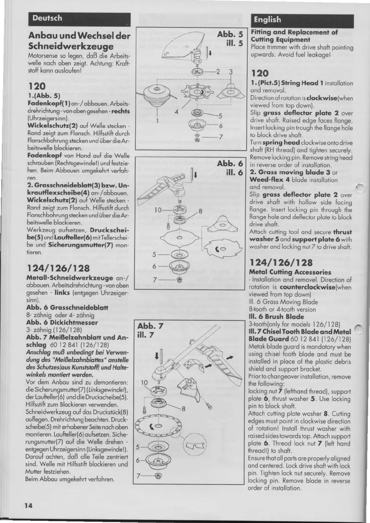
r20
r.(abb.
5)
Fodcnkopfl
|
)on-l
obbouen.
Arbeits-
drehrichtung
-
von
oben
gesehen
-
rechts
(Uhrzeigercinn).
Wickclschutr(2)
ouf
Welle
stecken
Rond zeigl zum Flonsch.
Hilfsstift durch
Flonschbohruno stecken
und i;ber d ie,qr
beits*elle bloc[ieren.
Fodcnkod von Hond
ouf die Welle
schrouben
(Rechrge*inde
ll und festzie-
hen.
Eeim Abbouen umoeleha verfoh.
ren.
2.
Grossthncidcblon(3)
bzw. Un.
kroutfl
exrtheibc(4)
on-lobbouen.
Wickclsthutr(2)
ouf
Welle
stecken
-
Rond
zeist zum Flonsch.
Hilßdih durch
Flonschbohrung
stecken
und uber dieAr
beitswelle blo<kieren.
Werkzeug
oufsetzen, Dru.k..hei.
be(5)
und taufellcr(6) mitTellerschei'
be und
Sichcrung;muner(7) mon-
r24lr26/128
lletof f
-Schneidwerkr,cugc
on-
/
obbcuen. Arbeitsdrehrichtuno
-
von
oben
gesehen
-
links
{engegen-Uhrzeiger-
Abb.
6 Groischn€id€bldtt
8- zöhnis oder 4- zöhnig
Abb, 6 Di.ki.htmesrer
3
zöhnis
1126/128)
Abb.
7 Mcißelzohnblqtt
und An.
..hlog 60 1 2 8A1
11
26
/
1 28|,
Änxhhg
nvß unbdingt
bi Verwen-
dung des
"hlcißr'lzohnbhttes"
onstelle
&s *hvrzeslous Ktnsßrü
und llolre-
winkels
montla,n warden.
Vor
dem Anbou sind zu
demontieren:
die SicherungsmuEe(7)
(li
nksge-inde!|,
der l,oukeller(6)
und die Druckscheibel5l.
Hilksfih zum
Blockieren
verwenden.
Schneidwerkzeug ouf do! Drucksruck(8)
oufl
egen.
Drehrichrung
beochten. Drlrck'
scheibe(5l mit erhobener Seie noch
oben
montieren.
Loufcller(6)oufserzen.
Siche-
rungsmuferlTl
ouf die
Welle
drehen
'
entg€en
Uhrzeigersinn
([hk€ewindel).
Dorouf
ochten. doß olle Teile zenrriert
sind. Welle
mir
Hilfsstift
blockieren und
Mutter festiehen.
Beim Abbou
umgekeh+
verfohren.
t4
Fitting
ond Rcplocoment
of
Cutling Equipment
Ploce
lrimmer wift
drive
shofi
pointing
upwords. Avoid
fuel leokogel
r20
l.
(Picr.sl
Slring Heod I instollorion
Direction
ol rolotion is.lo<kwi*{when
viewed from
lop
down).
Slip gro3r
dcfle.tor plotc
2 over
drive
shoft. Roised edge loces
flonge.
Ins€
locking pin
hough the flonge
hole
to
block
drive shoft.
Turn
spring heodclockwise
ontodrive
shoft
(RH
threod)
ond tighten
securely.
Removelocking pin.
Remove slring heod
in reveße
order of inslollotion.
2,
Grors moving
blode
3
or
W.cd-flox 4
blode instollotion
ond removol.
Slip groß
defl.<to. plotc
2 over
drive
shoh with hollow
side focing
flonge.
Inserl locking pin
firough the
flonge hole
ond deflector
plote
to block
drive
shoh.
Anoch
cuting lool ond
secure fhrud
wosher5
ond support plqfe
6
with
wosherond
locling
nut Z to drive
shoft.
r24/r26/r28
,$.lol
Cutling A..€'5orie.
'lnstollolion
ond removel.
Direclion of
rototion is
aounl€r.lo<kwirc(when
viewed
from top
downl
lll. 6 Gross Moving
Blode
SJooth
or
4Joolh
version
lll
6
Brurh
Blode
3-tooth(only for models l2ol)
281
lll. 7 Chirel Toorh
Blode ond ,ilerol
'
Blode
Guord
60
l2
841(126/128)
Metok blode guord is
mondobrywhen
using chisel fooih
blode ond must
be
instolled
in ploce
of
the plostic
debris
shield ond suppod
brocket.
Prior lo chongeover in
sto llofion, remove
the following:
locking
nur T
(lehhond
$reod),
support
plole
6, thrusi wosher
5. Use locking
pin
to
block shoh.
Attoch
cutling
plote
woshef
8. Cufing
edges must point
in cloci(wise
direction
o{ rololionl
Insloll lhrust wosher
with
roised
sidestowords top. Afloch
supporl
plote
6.
Threod
locl nut 7
{lefi
hond
threodl) to
shofi.
Ensure thol
oll
ports
ore
properly
oligned
ond centered.
Lock drive shofiwith lock
pin.
Tighlen lock
nut securely. Remove
locking pin. Remove
blode in reverse
order ofinstollolion.
abb.
5
iil.
5
6D_2 3
rr-
l
t#R ,A
r!%249=\
,/-
a
@_-------s
g-6
Ir
abb.
6
i[.
6
lo_f.e a
!@"
J
\.9-l
-
\<g
7_A
'SJf
 Loading...