N 15-M – Subject to technical changes 06.07
5
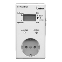
ST-Control - Operation
Function check
The ST-Control constantly monitors all sensors and per-
forms a plausibility check of solar usage. If no errors are
displayed, the solar system is correctly functioning.
If one of these displays to the right appears during operati-
on, the installer must be informed. In the case of a sensor
short circuit or interruption, the solar pump is switched off
until the input value is plausible again.
Operation
• Yellow button (“Anzeige”, display): By pressing this but-
ton, the numeric values of the sensors and target values
are
displayed one after the other. A black bar indicates the
designation of each numeric value.
• Blue button (“Ändern”, change): Setting the numeric
values (upward counting). If the bar displays “Solar-
pump”,
Error messages
If displays such as “Er1”, “Er2” or “Er3” appear, an error
is present in the EEPROM. The cause can be an overvolta-
ge, for example. Press the yellow button to reinitialize the
EEPROM. If the error occurs again thereafter, inform
the installer.
you can switch from automatic mode (“A”) to manual
mode (“H”).
• LED (“Solarpumpe”, solar pump): If the solar pump is
active, this is displayed by the LED next to the display.
The following displays may occur:
• “FF1”: Interruption of the collector sensor T
K
• “FF2”: Interruption of the storage tank sensor T
S
• “FF3”: Short circuit in the collector sensor T
K
• “FF4”: Short circuit in the storage tank sensor T
S
• “FF5”: Extended period of exceeding the operating tem-
perature difference. That means solar heat can
only be poorly utilized. There is probably a mal-
function in the solar circuit (e.g. insufficient flow).