EasyManuals Logo

SOMFY SOLIRIS Uno User Manual

SOMFY SOLIRIS Uno
6 pages
To Next Page IconTo Next Page
To Previous Page IconTo Previous Page
Page #2 background imageLoading...
Page #2 background image
SOLIRIS Uno
2
2 x
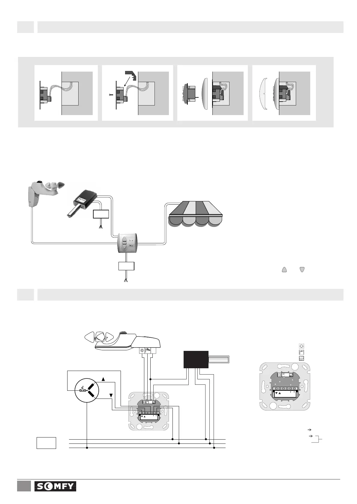
Connect the wires to the termi-
nals of the connecting bracket
in accordance with the terminal
layout (chapter 2.2).
Press the safety cover onto the
back of the bracket then fit this
one on the recessed box.
To remove the safety cover,use a screw-
driver to press gently in the slot provided in-
side the terminal block.
Plug the SOLIRIS Uno control
unit into the bracket,together
with the cover frame.
When setting (chapter 3) and
programming (chapter 4) is
completed,the cover plate can
be clipped onto the control unit.
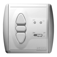
Terminal layout2.2
N
L
N
Soliris Uno connecting
Bracket
Terminal layout
Main Phase (L )
Main Neutral (N )
Motor Neutral (N)
Motor Up ()
Motor Down ()
N is bridged
internally
Common (C)
Sun sensor ( )
Wind sensor ( )
Rain sensor ( )
C
Mounting2.1
Test: When operating power has been connected,the direction of
the motor can be tested using the and buttons.
Soliris sensor
Rain sensor
Soliris Uno
4 x 0,75 mm
2
2 x 0,75 mm
2
3 x 0,75 mm
2
Supply
3 x 1,5 mm
2
Supply
3 x 1,5 mm
2
We reserve the right to make changes due to technical improvements.
SOLIRIS Uno is suitable for mounting in a 60 mm Ø concealed connection box or suitable surface mounting cap (Somfy accessories).
N
L
N
C
SUPPLY
230V 50Hz
Phase
Neutral
Earth
LT motor
DOWN
PE
N
UP
Soliris sensor
Soliris uno
C
Rain sensor
brown
brown
blue
blue
yellow/green

Questions and Answers:

Question and Answer IconNeed help?

Do you have a question about the SOMFY SOLIRIS Uno and is the answer not in the manual?

SOMFY SOLIRIS Uno Specifications

General IconGeneral
BrandSOMFY
ModelSOLIRIS Uno
CategoryControl Systems
LanguageEnglish

Related product manuals