7
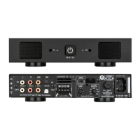
There are three options when connecting audio inputs
to the amplier:
Zone Line In Connectors: Use the local inputs to
dedicate one audio source to its corresponding zone
Bus A Input: Use the Bus A input to pass an
additional audio source, such as paging to any of the
Bus B Input: Use Bus B input to pass an additional
audio source, such as door chimes to any of the
BUS THRU Outputs
Each of the Bus Inputs provide non-buffered loop
connected in series will depend on the output capability
and RIGHT IN connections passes through to the LEFT
BUS A SUB Out
BUS A has subwoofer output connection, which sums
Setting the X-OVER switch to 80Hz or 120Hz will apply a
The 80Hz setting is the proper setting for most
subwoofer applications when used with large and
used with smaller main speakers or when more bass is
Connect a stereo line-level source with an RCA cable
Connect a single RCA cable from the SUB OUT jack
to the line-level input on a powered subwoofer, such
Figure 4: Using the Subwoofer Line-Level Output with the
Bus A Inputs (not applicable with the Bus B or local inputs)
SUB OUT
is being used in bridged mode (8 ohms minimum), use
the Zone IN connection labelled “BRIDGE” as described
Input DIP Switch Assignments
The DIP switches enable one or more audio sources to be
played through one or more speaker outputs
to the local (direct) source, Bus A signal input and/or Bus
DIP switch to ‘ON
Two zone example, the home could be subdivided into
into Bus A and a second source into Bus B (not into the
DIP switches
Control system example, the input connections can all be
local for a discrete four zone system with Bus A switched
sources connected to the various inoputs and the DIP
3
1
ZONE 1 ZONE 2 ZONE 4ZONE 3
Figure 5: Input DIP Switches
3
1
ZONE 1 ZONE 2 ZONE 4ZONE 3
Zone Trim Controls
is a TRIM control, not a volume knob, so the minimum
gain setting (fully counter-clockwise) will not turn off
Figure 6:
Volume Control
speakers distort, thereby preventing
controls also allow balancing of
the sound levels of different zones
or the outputs of the right and left
channels to compensate for various
room characteristics or seating
3
1
ZONE 1 ZONE 2 ZONE 4ZONE 3
IMPORTANT: DO NOT COMBINE NEGATIVE TERMINALS. THE
AMP IS NOT COMMON GROUND TYPE ARCHITECTURE.
 Loading...