8
AMPLIFIERS POWER REQUIREMENTS:
8-50 100-120VAC Max Power All Channels 8 ohm or 4 ohm 600W 3 (120VAC) 4
(120VAC)
1/8 Power All Channels <200W 9 (120VAC) 12 (120VAC)
@ Idle 30W
8-50 220-240VAC Max Power All Channels 8 ohm or 4 ohm 600W 6 (230VAC) 8
(230VAC)
1/8 Power All Channels <200W 18 (230VAC) 24 (230VAC)
@ Idle 30W
16-50 100-120VAC Max Power All Channels 8 ohm or 4 ohm 600W 3 (120VAC) 4
(120VAC)
1/8 Power All Channels <200W 9 (120VAC) 12 (120VAC)
@ Idle 50W
16-50 220-240VAC Max Power All Channels 8 ohm or 4 ohm 600W 6 (230VAC) 8
(230VAC)
1/8 Power All Channels <200W 18 (230VAC) 24 (230VAC)
@ Idle 50W
NOTE: THE AMPLIFIERS DO NOT SUPPORT MATRIX VOLUME
CONTROL. RELATIVE SOURCE LEVELS BETWEEN ZONES AND
ZONE/BUS INPUTS MUST BE SET AT THE SIGNAL SOURCE.
IMPORTANT: USE CAUTION WHEN SETTING VOLUME LEVELS
EITHER ON THE AMPLIFIER OR AN AUDIO SWITCHER AS NOT
TO OVERDRIVE AND POSSIBLY DAMAGE SPEAKERS. VERIFY
ALL SOURCES AS OUTPUT VOLTAGE VARIES FROM DEVICE TO
DEVICE.
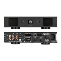
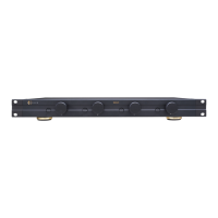
Figure 8:
Speaker Connectors
The removable Speaker Block
Connectors used on the
bare wires are in contact with
have four terminals actuated by
can be used for normal stereo or
NOTE: ALWAYS CHECK LOCAL BUILDING CODES BEFORE
INSTALLING WIRE IN WALLS OR CEILINGS.
IMPORTANT: THE MINIMUM SPEAKER IMPEDANCE FOR
BRIDGED OPERATION IS 8 OHMS. DO NOT CONNECT
SPEAKERS RATED AT LESS THAN 8 OHMS IN BRIDGED MODE.
THE AMPLIFIER CAN RUN HOT, MAY GO INTO PROTECTION
AND HAVE A REDUCED LIFESPAN.
Bridge Mode/Bridging
the phase to the right channel and drives the left and
ZONE 1
right channels together in series to generate higher
additional power in bridge mode can be advantageous
for driving a passive woofer such as the Visual
Performance VP85RW or an 8 Ohm outdoor satellite and
ZONE 1
Figure 10: Bridging Channels
Figure 9:
Bridging Channels
For bridging, use the left Local Input or the left Bus Input
Use the DIP switch to select the input you would like to
connector marked “-” (third speaker lead position
3
1
ZONE 1 ZONE 2 ZONE 4ZONE 3
 Loading...