EasyManua.ls Logo

Sonance DSP 2-750 MKII User Manual

Sonance DSP 2-750 MKII
20 pages
To Next Page IconTo Next Page
Page #1 background imageLoading...
Page #1 background image
SONAMP MULTI-CHANNEL POWER
AMPLIFIER WITH SonARC V2
INSTRUCTION MANUAL
DSP 2-750 MKII
Sonance DSP2-750 MKII A mplifier
Rear Panel 4/ 2/ 2018
Die Line Do N ot Print
Prints W hite
1L
1R
DSP 2-750 MKII
1-R1-L 2-R2-L
IN IN
OUTOUT
DSP 2-750 MKII
S/N
1 - RIGHT
1 - LEFT
+ +
__
+
_
BRIDGE
4 Ω MIN
+
+
_ _
VOLTAGE TRIGGER
3-30 volts AC/DC
IN OUT
IN
OUT
IR
CONTROL
IR
STATUS
TCP/IP
DEFAULT IP
192.168.1.50
T10AL/250VAC
CAUTION
REPLACE FUSE ONLY WITH SAME
TYPE AND RATING OF FUSE
ATTENTION
REMPLACER UNIQUEMENT AVEC
LE MEME TYPE ET CALIBRE DU
FUSIBLE
AC 100-120V ~ 60Hz
AC 220-240V ~ 50Hz
CAUTION
RISK OF ELECTRIC SHOCK
DO NOT OPEN
AVIS
RISQUE DE CHOC ELECTRIQUE
NE PAS OUVRIR
Question and Answer IconNeed help?

Do you have a question about the Sonance DSP 2-750 MKII and is the answer not in the manual?

Sonance DSP 2-750 MKII Specifications

General IconGeneral
BrandSonance
ModelDSP 2-750 MKII
CategoryAmplifier
LanguageEnglish

Summary

Important Safety Information

Introduction and Setup Basics

Box Contents

Lists all items included in the product packaging for user verification.

Amplifier Placement Guidelines

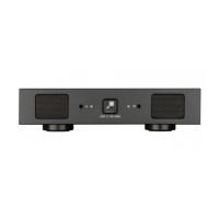
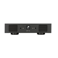
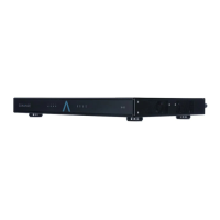
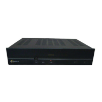
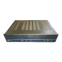
Recommendations for optimal amplifier positioning to ensure ventilation and performance.

Front Panel Overview

Front Panel Components Identification

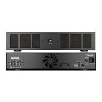
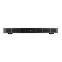
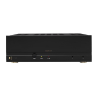
Identifies and describes the function of each control on the front panel.

Rear Panel Overview

Rear Panel Connection Ports

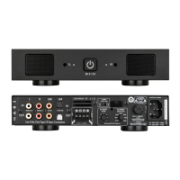
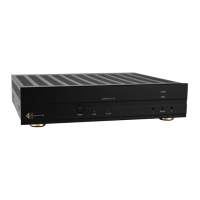
Details the various input, output, and power connectors on the rear panel.

Front Panel Controls and Indicators

Power, Indicators, and Volume Controls

Explains the power button, status LEDs, and volume adjustment features.

Control Interfaces (Auto On, IR, IP)

Details how to use Auto On, IR, and IP control for amplifier operation.

Rear Panel Connectivity

Audio Input/Output and Speaker Connections

Guides on connecting audio sources and speakers to the amplifier.

Amplifier Powering and Connections

Connecting the Power Cord

Instructions for properly connecting the amplifier's power cord.

Audio Source Connections

Steps for connecting various audio sources to the amplifier's inputs.

Power Requirements and Breaker Sizing

Specifies power consumption and recommended circuit breaker sizes.

Speaker and Source Connectivity

Speaker Connection Details

Proper methods for connecting speaker wires, including bridging.

Bridging Channels for More Power

Instructions on how to bridge amplifier channels for increased output.

Volume Level Control

Amplifier Protection and Installation

Protection Circuitry and LED Status

Explains the amplifier's protection systems and LED indicators.

Rack Ear Installation and Stacking

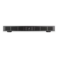
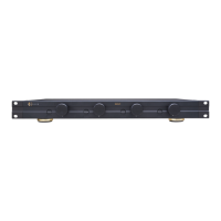
Guides on installing rack ears and stacking amplifiers.

SonARC Software Configuration

Connecting to SonARC Homepage

Steps to establish a network connection to the SonARC software interface.

DSP Preset and Input/Source Setup

Configuring DSP presets and assigning audio input sources to channels.

Output Settings and Amplifier Identification

Output Volume and Naming

Setting output volume levels and naming amplifier channels.

Amplifier Identification and Info

Features for identifying the amplifier during setup and entering descriptive info.

Advanced Setup Overview

IP Configuration and Power Management

IP Setup and Network Masking

Configuring IP address, subnet mask, and DHCP settings.

Auto On and Sleep Mode Settings

Setting up automatic turn-on and sleep mode behavior.

Backup, Restore, and Print Options

Managing amplifier settings via backup, restore, and print functions.

In/Out and EQ Settings

Input and Output Configuration

Defining input names, trim levels, and output settings.

Source Selection and Mixing

Selecting primary/secondary sources and configuring mix/mute modes.

EQ Setting Tab Overview

Introduction to the Equalizer (EQ) settings tab for audio tuning.

DSP Preset Management

Assigning and Editing DSP Presets

Selecting, assigning, and customizing DSP presets for speakers.

Importing and Exporting Presets

Managing DSP presets through import and export functionalities.

Test Signals and Frequency Response

Using test signals and understanding frequency response graphs.

Advanced Audio Processing

Parametric EQ and Filters

Adjusting parametric EQ settings and filter parameters for audio tuning.

Crossover and Limiter Settings

Configuring crossover points and output limiting for speaker management.

Specifications

Appendices and Resets

LED Indicators and DHCP Reset

Explanations of LED indicators and steps for DHCP reset.

Amplifier Factory Reset Procedure

Detailed instructions for performing a factory reset on the amplifier.

Auto On/Sleep Mode Details

Comprehensive table detailing Auto On and Sleep mode configurations.

Troubleshooting Common Issues

Power and Audio Problems

Solutions for common power-on and no-audio issues.

Network and IR Control Problems

Troubleshooting network connectivity and infrared control failures.

Channel and Protection Troubleshooting

Resolving Channel Output Problems

Diagnosing and fixing issues related to specific channel outputs.

Addressing Protection LED Indicators

Steps to resolve problems indicated by protection LEDs.

Factory Reset Procedure

Warranty Information

Related product manuals