EasyManua.ls Logo

Sonance 8-50 - User Manual

Sonance 8-50
2 pages
Print Icon
To Next Page IconTo Next Page
Loading...
MULTI-CHANNEL POWER AMPLIFIER 8-50 | 16-50
QUICKSTART GUIDE
APPLICATION NOTES
BUS CONNECTIONS
BUS A LOW PASS X-OVER: Subwoofer crossover
can be set to 80Hz or 120 Hz. High Pass x-over will
impact the Left and Right BUS A channels as well
Powering a Passive Subwoofer: Use RCA from
subwoofer output to an unused discrete line input
in BRIDGE mode
NOTE: Setting the X-OVER to 80Hz or 120Hz will
crossover the signal for any zone output using BUS A
(80Hz and above, or 120Hz and above)
Connect source audio cables to Bus A, Bus B, or
Direct, making sure to adjust DIP switch to appropriate
selection for each Zone Output.
SENSE SWITCH FOR POWER SELECTION
Switch Set to “OFF”, Amp is
always powered on, ready to
play audio
Switch Set to VOLTAGE”, Amp
will power on with 12V DC applied.
Use the output to pass through to
other amps
Switch Set to “AUDIO”, Amplifier will power on
with audio signal after 4-6 seconds, and o with a
loss of audio signal after 15 minutes
ZONE INPUT CONNECTIONS
Use RCA connections from discrete source to play
to associated zone (discrete inputs are always
active)
Use DIP switch if using Bus A, Bus B, or to bridge
the speaker output
Note the alternating Left or Right Discrete input
for bridged mode outputs
Zone Level Control: Adjust in small increments to
correct output gain as needed
DIP switches to enable Bus A input, Bus B input, and
Bridge mode on each zone.
BUS INPUTS AND DIP SWITCHES
DIP Switch selections can include one or both BUS
inputs, and or BRIDGE. When more than one BUS
input is selected on the DIP switch, the audio signals
will be mixed and all will be played back in that zone.
This can be useful when one BUS includes paging or a
doorbell signal
SPEAKER CONNECTIONS
Attach speaker wire (up to 12 gauge) with
included speaker block connectors for each zone
Wiring for Bridge Mode: Use Left Positive and
Right Negative connections
Accepts speaker wire, up to 12 gauge. Note polarity
when connecting.
NOTE: Do not combine negative terminals. The amp is
not common ground type architecture.
BOX CONTENTS
(1) Quickstart Guide
(1) Sonance Amplifier (8-50 or 16-50 model)
(1) IEC Power Cord (Region Dependent)
(4) Amp Feet
(2) Rack Ears and Screws
(4) Block Connector for Speaker Outputs
(1) Block Connector for Voltage Trigger
3
1
ZONE 1 ZONE 2 ZONE 4ZONE 3
3
1
ZONE 1 ZONE 2 ZONE 4ZONE 3
3
1
ZONE 1 ZONE 2 ZONE 4ZONE 3
3
1
ZONE 1 ZONE 2 ZONE 4ZONE 3
Question and Answer IconNeed help?

Do you have a question about the Sonance 8-50 and is the answer not in the manual?

Overview

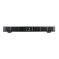
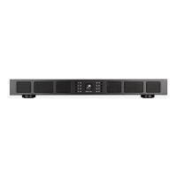
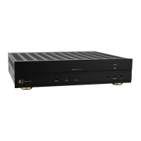
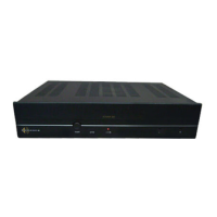
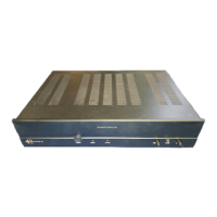
The Sonance Multi-Channel Power Amplifier, available in 8-50 and 16-50 models, is designed to provide robust audio amplification for multi-zone installations. This quickstart guide outlines its key features, connections, and operational considerations.

Function Description

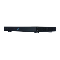
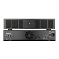
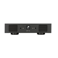
The amplifier serves as a central hub for distributing audio to multiple zones, offering flexible input and output configurations. It supports various power-on modes, including always-on, 12V trigger, and audio-sense, making it adaptable to different system integration needs. The device is capable of bridging speaker outputs to deliver higher power to individual zones, and it includes crossover settings for subwoofer integration.

Important Technical Specifications

  • Models: 8-50 (8 channels, 50W per channel) and 16-50 (16 channels, 50W per channel).
  • Power Input: IEC Power Cord (region dependent).
  • Speaker Outputs: Block connectors for speaker wire up to 12 gauge.
  • Voltage Trigger: Block connector for 12V DC trigger input/output.
  • Bus Inputs: RCA connections for Bus A and Bus B, with pass-through options.
  • Discrete Inputs: RCA connections for individual zones.
  • Subwoofer Output: RCA connection for Bus A subwoofer output.
  • Crossover Settings (Bus A): Selectable 80Hz or 120Hz for low-pass (subwoofer) and high-pass (Left/Right Bus A channels).
  • Power Modes:
    • OFF (Always On): Amplifier is continuously powered, ready for audio playback.
    • VOLTAGE (12V Trigger): Amplifier powers on with 12V DC applied to the trigger input. Output allows pass-through to other amplifiers.
    • AUDIO (Audio Sense): Amplifier powers on with an audio signal after 4-6 seconds and powers off after 15 minutes of no audio signal.
  • Protection: Features a protect mode indicator (Red LED) that requires a power cycle to reset.
  • Clipping: Includes clipping indicators (Yellow LED on front panel, Red LED on rear panel) to signal excessive output.

Usage Features

Box Contents

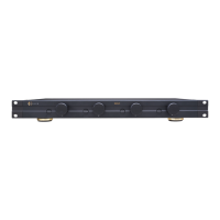
The amplifier comes with a quickstart guide, the amplifier unit itself (8-50 or 16-50 model), an IEC power cord, four amp feet, two rack ears with screws, four speaker block connectors, and one voltage trigger block connector.

Zone Input Connections

  • Discrete Sources: RCA connections allow direct input to an associated zone, with discrete inputs always active.
  • Bus Inputs: DIP switches enable selection of Bus A, Bus B, or both. When multiple BUS inputs are selected, their audio signals are mixed and played in that zone, useful for paging or doorbell signals.
  • Bridged Mode: DIP switches also allow bridging of speaker outputs for higher power. Note that bridged mode outputs use alternating Left or Right Discrete inputs.
  • Zone Level Control: Individual level controls for each zone allow fine-tuning of output gain.

Bus Connections

  • Bus A Low Pass X-OVER: Subwoofer crossover can be set to 80Hz or 120Hz. This setting also affects the high-pass crossover for the Left and Right Bus A channels.
  • Powering Passive Subwoofers: An RCA connection from the subwoofer output can be routed to an unused discrete line input in BRIDGE mode to power a passive subwoofer.
  • X-OVER Note: Setting the X-OVER to 80Hz or 120Hz will crossover the signal for any zone output using Bus A (80Hz and above, or 120Hz and above).

Speaker Connections

  • Wiring: Attach speaker wire (up to 12 gauge) using the included speaker block connectors. Observe polarity when connecting.
  • Bridge Mode Wiring: For bridged mode, use the Left Positive and Right Negative connections.
  • Important Note: Do not combine negative terminals, as the amplifier does not use a common ground architecture.

Front Panel Indicators

  • System Status Indicator:
    • White: Amp is in Standby mode.
    • Blue: Amp is Active.
    • Red: Amp is in Protect mode (requires power cycle to reset).
  • Zone Indicators:
    • White: Amp channel is on, no audio present.
    • Blue: Amp channel is on, audio present.
    • Red: Amp channel in Protect mode (requires power cycle to reset).
    • Yellow: Clipping amplifier output.

Rear Panel Indicators

  • Clip Indicators: Red LEDs indicate that the zone signal is too high, causing amplifier clipping. Resolve by lowering the source input signal or volume.

Rear Panel Layout (8-50 Model)

  1. System Status Indicator
  2. Zone Status Indicator
  3. AC Power Socket
  4. AC Power Switch
  5. Sense Switch (for power selection)
  6. Voltage Trigger Connector
  7. Bus A Input / Thru
  8. Crossover Switch (Bus A)
  9. Sub Out (Bus A)
  10. Bus B Input / Thru
  11. Zone Configuration DIP Switch
  12. Zone Level Control
  13. Zone Speaker Outputs
  14. Zone Local Inputs
  15. Zone Clip Indicator

Rear Panel Layout (16-50 Model)

The 16-50 model features a similar layout but with double the number of zone-specific controls and outputs (Zone 1-8 and Zone 9-16).

Maintenance Features

  • Troubleshooting Protect Mode: If the red protect mode indicator illuminates, power cycle the amplifier and check all connections.
  • Troubleshooting Clipping: If the yellow (front panel) or red (rear panel) clipping indicators illuminate, lower the source input signal or volume to prevent distortion and potential damage.
  • Firmware/Updates: For the latest product specification information, refer to the Sonance website.
  • Technical Support: Contact Sonance technical support at 949.492.7777 or visit www.sonance.com.
  • Installation: Ensure all system connections are made before plugging the power cord into the outlet.
  • Rack Mounting: The amplifier includes rack ears and screws for secure installation in a rack.
  • Feet: Four amp feet are provided for standalone placement.

The Sonance Multi-Channel Power Amplifier is designed for reliable and flexible audio distribution in various residential and commercial applications, emphasizing ease of setup and robust performance.

Sonance 8-50 Specifications

General IconGeneral
BrandSonance
Model8-50
CategoryAmplifier
LanguageEnglish

Related product manuals