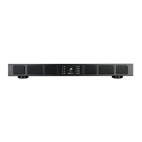
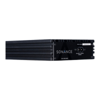
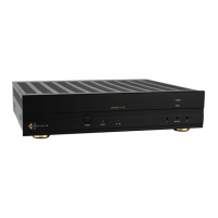
Sonance 8-50 MULTI-Channel Amplifier
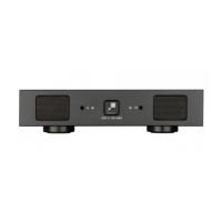
FRONT PANEL
1. System Status Indicator
2. Zone Status Indicator
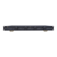
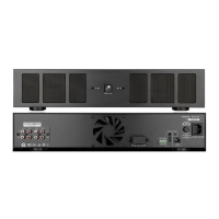
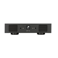
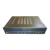
REAR PANEL
3. AC Power Socket
4. AC Power Switch
5. Sense Switch
6. Voltage Trigger Connector
7. Bus A Input / Thru
8. Crossover Switch (Bus A)
9. Sub Out (Bus A)
10. Bus B Input / Thru
11. Zone Configuration DIP Switch
12. Zone Level Control
13. Zone Speaker Outputs
14. Zone Local Inputs
15. Zone Clip Indicator
1
64
2
5
ZONE 1 ZONE 2 ZONE 4ZONE 3
3
9
8 10
13
11 14
12 157
Scan QR code for additional information.
For technical support call 949.492.7777
or visit www.sonance.com
IMPORTANT: DO NOT PLUG THE
POWER CORD INTO THE OUTLET
UNTIL ALL SYSTEM CONNECTIONS
HAVE BEEN MADE.
©2022 Sonance. All rights reserved. Sonance is a registered trademark of
Dana Innovations. Due to continuous product improvement, all features and
specifications are subject to change without notice. For the latest Sonance product
specification information visit our website: www.sonance.com
SONANCE • 991 Calle Amanecer • San Clemente, CA 92673 • (949) 492-7777
07.22.2022
Rear Panel
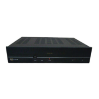
Front Panel
LED STATUS INDICATORS
Front Panel System Status Indicator
• White: Amp has power and is in Standby mode
• Blue: Amp has power and is Active
• Red: Amp is in protect mode. Power cycle
amplifier to reset, check all connections
Front Panel Zone Indicators
• White: Amp channel is on, no audio present
• Blue: Amp channel is on, audio present
• Red: Amp channel in protect mode. Power cycle
amplifier to reset, check all connections
• Yellow: Clipping amplifier output
Rear Panel Clip Indicators
• Red: Zone Signal is too high, clipping amp output.
Resolve by lowering source input signal or volume
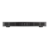
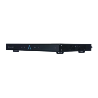
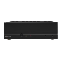
Sonance 16-50 MULTI-Channel Amplifier
ZONE 1 ZONE 2 ZONE 4ZONE 3
ZONE 5 ZONE 6 ZONE 8ZONE 7
Rear Panel
Front Panel