8
IMPORTANT: ALLOWING THE AMPLIFIER TO OPERATE WITH ONE OR
MORE CHANNELS IN PROTECT MODE FOR AN EXTENDED PERIOD OF
TIME CAN DAMAGE THE AMPLIFIER.
Protection Circuitry and LEDs
TheSonampampliershaveamulti-stageprotectionsystemto
preventdamagetoyouramplierandspeakers.
Amplier Channel Protection DSP 2-750 MKII
If a channel encounters a short-circuit (in bridge mode the
protection circuitry will sense a short circuit across both positive
speaker terminals), or extremely low impedance will cause the
aectedchanneloutputstoautomaticallymute.Theoutputof
theaectedchannelwillremainmuteduntilthefaulthasbeen
corrected.Onlytheaectedchannelsoutputwillmute,allother
channels will continue to operate normally.
Amplier Channel Protection Indication
OnthefrontpaneloftheSonampDSP2-750MKIIampliersare
dual color LEDs that illuminate to indicate the current operating
statusofeachamplierchannel.
When the LED blinks red this is an indication that the channel is
being over driven.
WhentheLEDlightsaresolidredthisisanindicationtheamplier
is in protect mode. While in protect mode the LED lights will
periodically light green to retest the output to determine if the short
has been removed. Protect mode could be caused by a short in
thewire,overheatingoftheamplierorpossiblyaninternalproblem
withtheamplier.
Iftheampliersensesaverylowimpedanceorashortonits
outputs, then it will mute its output and the protection LEDs will
turn red. The output will remain muted until the fault is cleared.
Check the rear panel block connector for shorted wire strands
or reduce the number of speakers connected in parallel to the
amplieroutputs.Sonanceampliersareratedfora4ohmloador
higher, such as two pair of eight ohm speakers.
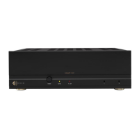
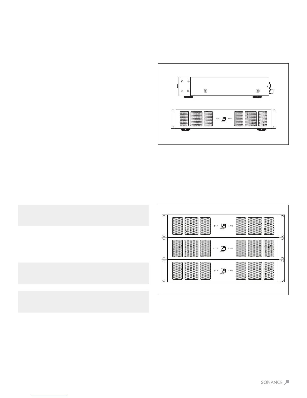
Rack Ear Installation DSP 2-750 MKII
The DSP 2-750 MKII ships with two rack ears. Unscrew the four
Phillips head screws (M4 x 0.7 pitch x 10mm long) found on each
sideoftheleftandrightforwardsectionofamplier.Usethese
screwstoconnecttheincludedrackearstotheamplier
(see Figure 15).
Figure15:RackEarInstallationDSP2-750MKII
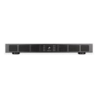
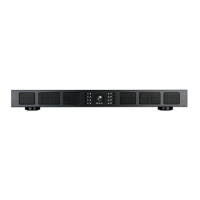
Amplier Stacking
The DSP 2-750 MKII is capable of being directly stacked with the
feet removed (see Figure 16) for use in low to moderate output
applications. For high-output applications, it is recommended to
leaveatleast1Uspacebetweenampliersforincreasedventilation.
Itisnotrecommendedtostackmorethanthreeampliershigh
without spacing.
MKII
MKII
MKII
Figure16:StackedCongurationDSP2-750
IMPORTANT: ANY TIME THE PROTECTION CIRCUITS ARE TRIGGERED,
UNPLUG THE AMPLIFIER’S POWER CORD FROM THE WALL OUTLET
BEFORE TROUBLESHOOTING.
Amplier Power Supply Protection DSP 2-750 MKII
Theamplieralsohasprotectionforthepowersupply.Ifthepower
supply heat sink temperature exceeds the design maximum, the
protection circuit will activate, disconnecting all channel outputs.
This is indicated by a blinking light on the front panel power switch.
NOTE: IF SHELF MOUNTING, ATTACH THE FOUR INCLUDED FEET BY
SCREWING THEM INTO THE THREADED OPENINGS ON THE BOTTOM
CHASSIS. NO TOOL IS REQUIRED.
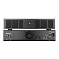
Front View
Side View Right
Front View
MKII

 Loading...