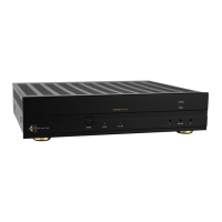
Sonance DSP2-750 MKII Amplifier
Rear Panel 4/ 2/ 2018
Die Line Do N ot Print
Prints W hite
1L
1R
DSP 2-750 MKII
1-R1-L 2-R2-L
IN IN
OUTOUT
DSP 2-750 MKII
S/N
1 - RIGHT
1 - LEFT
+ +
__
+
_
BRIDGE
4 Ω MIN
+
+
_ _
VOLTAGE TRIGGER
3-30 volts AC/DC
IN OUT
IN
OUT
IR
CONTROL
IR
STATUS
TCP/IP
DEFAULT IP
192.168.1.50
T10AL/250VAC
CAUTION
REPLACE FUSE ONLY WITH SAME
TYPE AND RATING OF FUSE
ATTENTION
REMPLACER UNIQUEMENT AVEC
LE MEME TYPE ET CALIBRE DU
FUSIBLE
AC 100-120V ~ 60Hz
AC 220-240V ~ 50Hz
CAUTION
RISK OF ELECTRIC SHOCK
DO NOT OPEN
AVIS
RISQUE DE CHOC ELECTRIQUE
NE PAS OUVRIR
7
Bridging Channels DSP 2-750 MKII
Figure13:VolumeLevelControl
Figure11:BridgingChannels
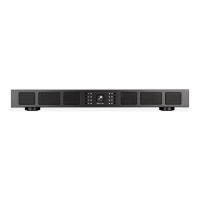
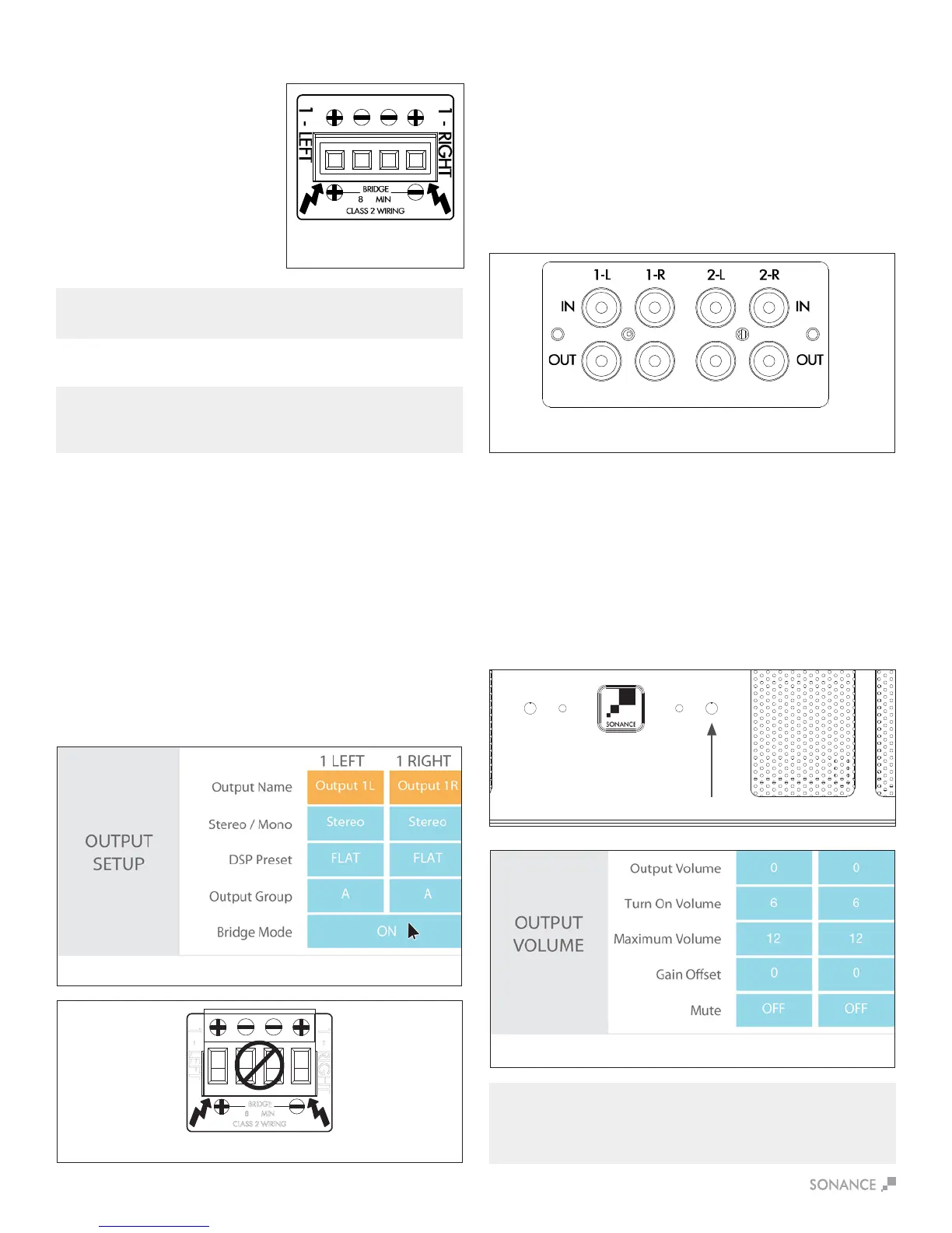
Volume Level Control
Volume can be controlled from the individual recessed volume level
control screws, located on the front panel and from SonARC (see
Figure 13). These volume controls balance the desired sound levels
perchannel.Volumecanbecontrolledthreedierentwayswith
SonARC v2 (see Figure 14).
1. Output volume 2. Turn on volume 3. Maximum volume
Output volume ranges between -70 to 12. The volume level
controls are set at +12 by default.
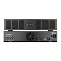
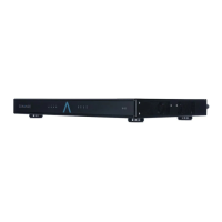
Source Connections DSP 2-750 MKII
On the left side of the rear panel are the audio inputs for the left
and right channels. In addition to the left and right inputs there are
also loop outputs for each channel. The loop outputs allow multiple
amplierstosharecommonaudiosources.Theloopoutputson
theampliersarenotbuered.Thenumberofampliersthatcan
be connected in series will depend on the output level of your audio
source.ThesourceconnectedtotheLEFTandRIGHTLINEIN
InputspassthroughtheLEFTandRIGHTLINEOutputs
(see Figure 12).
LEVEL LEVEL
B
RIDGE
OFF ON
MONOSTEREO
12-50
S/N
VOLTAGE TRIGGER
IN OUT
AUTO ON
OFF
IN
O
UT
IN
OUT
1-LEFT 1-RIGHT
LEVEL LEVEL
B
RIDGE
OFF ON
MONOSTEREO
LEVEL LEVEL
B
RIDGE
OFF ON
MONOSTEREO
LEVEL LEVEL
B
RIDGE
OFF ON
MONOSTEREO
LEVEL LEVEL
B
RIDGE
OFF ON
MONOSTEREO
LEVEL LEVEL
B
RIDGE
OFF ON
MONOSTEREO
2-LEFT 2-RIGHT 3-LEFT 3-RIGHT 4-LEFT 4-RIGHT 5-LEFT 5-RIGHT 6-LEFT 6-RIGHT
LOCAL
B
USS A
B
USS B
LOCAL
B
USS A
B
USS B
LOCAL
B
USS A
B
USS B
LOCAL
B
USS A
B
USS B
LOCAL
B
USS A
B
USS B
LOCAL
B
USS A
B
USS B
CAUTION
RISK OF ELECTRIC SHOCK
D
O NOT OPEN
AVIS
RISQUE DE CHOC ELECTRIQUE
NE P
AS OUVRIR
LEFT RIGHT LEFT RIGHT
BUSS INPUT A BUSS INPUT B
1 - LEFT
BRIDGE
8 Ω MIN
CLASS 2 WIRING
T10AL / 250VAC
CAUTION
R
EPLACE FUSE ONLY WITH
SAME TYPE AND RATING
ATTENTION
REMPLACER UNIQUEMENT AVEC LE
M
EME TYPE ET CALIBRE DU FUSIBLE
2 - LEFT
2 - RIGHT
BRIDGE
CLASS 2 WIRING
3 - LEFT
3 - RIGHT
BRIDGE
CLASS 2 WIRING
5 - LEFT
5 - RIGHT
BRIDGE
CLASS 2 WIRING
6 - LEFT
6 - RIGHT
BRIDGE
CLASS 2 WIRING
4 - LEFT
4 - RIGHT
BRIDGE
CLASS 2 WIRING
VOLTAGE
AUDIO
3-30 VOLTS
AC or DC
8 Ω MIN 8 Ω MIN 8 Ω MIN 8 Ω MIN 8 Ω MIN
156 watts
AC 100-120V ~ 60Hz
AC 220-240V ~ 50Hz
Figure14:SonARCPageIn/OutSettingsOutputVolume
Speaker Connections
For the best sound you should use
premium speaker wire that complies
withreratingcodes.Besureto
check local codes governing wire
that may be installed within walls or
ceilings.Sonampampliersare
stable with any reputable brand of
speaker wire or cable. The Sonamp
ampliersusespeakerblock
connectors that can accommodate
up to 12 gauge wire (see Figure 9).
NOTE: ALWAYS CHECK LOCAL BUILDING CODES BEFORE INSTALLING
WIRE IN WALLS OR CEILINGS.
Figure 9
Speaker Connections
Bridging channels is accomplished using the SonARC v2 software.
OnthesecondpageinthesoftwareunderIN/OUTSettings,goto
the output setup area to bridge mode and make your selections
with the drop down buttons.
1.Usetheleftaudioinputwhenoperatingtheampliersoutputin
bridge mode (see Figure 10).
2.SelectONinthebridgemode(seegure10).
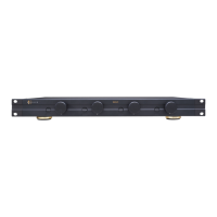
3.Connectthespeaker’s“+”leadtotheleftsideoftheconnector
marked“+”(seeFigure11).
4.Connectthespeaker’s“–”leadtotherightsideoftheconnector
marked“+”(seeFigure11).
5. Connect the line level audio input to the LEFT channel input on
theamplier.
IMPORTANT: THE MINIMUM SPEAKER IMPEDANCE FOR BRIDGED
OPERATION IS 8 OHMS. DO NOT OPERATE A ZONE IN THE BRIDGED MODE
INTO A SPEAKER THAT IS LESS THAN 8 OHMS NOMINAL IMPEDANCE.
Figure10:BridgingChannels
Figure12:SonampDSP2-750MKII
LeftandRightLineInputs/Outputs
IMPORTANT: USE CAUTION WHEN SETTING VOLUME LEVELS EITHER ON
THE AMPLIFIER OR AN AUDIO SWITCHER AS NOT TO OVERDRIVE AND
POSSIBLY DAMAGE SPEAKERS. VERIFY ALL SOURCES AS OUTPUT
VOLTAGE VARIES FROM DEVICE TO DEVICE.

 Loading...