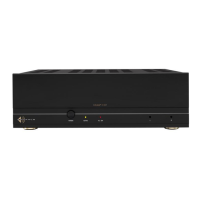
MULTI-CHANNEL POWER AMPLIFIER DSP 8-130 MKIII
QUICKSTART GUIDE
BOX CONTENTS
(1) Quickstart Guide
(1) Sonance DSP 8-130 MKIII Amplifier
(1) IEC Power Cord (Region Dependent)
(4) Amp Feet
(2) Rack Ears
(4) Block Connector for Speaker Outputs
(1) Block connector for Voltage Trigger
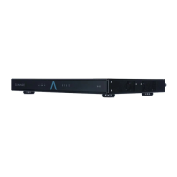
SOURCE CONNECTIONS
The DSP 8-130 MKIII ships with two Analog Input
Modules. By default, Inputs 1 through 4 are routed to
Zones 1 through 4, respectively. Dierent routing can
be configured through SonARC interface.
VOLTAGE TRIGGER CONTROL
The DSP 8-130 MKIII has a 3-30V (AC or DC) control
input. The factory default setting of the amplifier is
Always On or Audio-Sense. The Voltage Trigger can
be enabled within the SonARC interface.
IR CONTROL
The 3.5mm jack can be used to receive IR commands
from a distribution box or self-powered IR sensor. The
amplifier does not provide a voltage to IR sensors.
Refer to the DSP 8-130 MKIII webpage for specific IR
control codes. This feature is always active, and does
not need to be enabled in the SonARC interface.
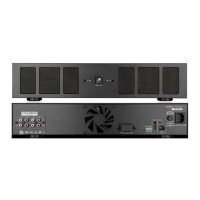
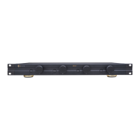
SPEAKER CONNECTIONS
NOTE: The DSP 8-130 MKIII is capable of driving 4
ohm stereo, 8 ohm stereo, or 8 ohm bridged mono
loads. Bridged mono load configurations require
selection in the SonARC interface.
1. Connect speaker wire (up to 12 AWG) to the
provided block connector. IMPORTANT: Keep all
wire strands inside the plastic shell. Damage may
occur if speaker wires short together or touch the
amplifier housing.
2. For bridged operation, connect speaker wires
from LEFT+ to SPEAKER+ and RIGHT+ to
SPEAKER -.
3. Plug the block connector into the amplifier and
check that there is no strain on the speaker wire.
Figure 2: Speaker Output
Figure 1: Source Connections
GETTING STARTED
The Sonance DSP 8-130 MKIII comes ready to play
audio out-of-the-box. Installers have the option to
set the amplifier up using the physical controls for
customization or the SonARC web interface (ethernet
interface required). Sonance suggests the following
installation sequence:
1. Place amplifier in a location away from moisture
and temperatures exceeding 100°F (38°C).
2. Connect Audio Inputs.
3. Connect Speaker Outputs.
4. Connect network jack with an ethernet cable from
the amplifier to a network hub or switch (see the
complete DSP 2-750 MKIII User’s Manual and the
SonARC guide for complete details).
5. For IR control, insert a mono 3.5mm plug (tip-
positive) into the 3.5mm jack labeled “IR Control”.
6. For Voltage Trigger, connect trigger lines to the
IN + and IN- terminals on the Voltage Trigger
terminal block.
7. Connect the power cord.
8. Confirm inbound audio feed signals have been
muted. Turn the amplifier power switch to the ON
position.
POWERING THE AMPLIFIER
Plug the provided 14 gauge EIA standard 120 Volt
grounded power cable into the IEC power connector.
IMPORTANT: Do not plug the power cord into the
wall outlet until all system connections are made.
RESET BUTTON
Pressing the RESET button for less than five
seconds will reboot the amp. Pressing the RESET
button between five and ten seconds will reset the
network settings to factory defaults (DHCP on).
Pressing the RESET button for greater than ten
seconds will perform a full factory reset, erasing
any EQ changes or other user settings.
DSP 8-130 MKIII
1
R
2R
3R
4R
1
L
2L
3L
4L
DSP 8-130 MKIII
1R
2R
3R
4R
1L
2L
3L
4L