5
Your wireless transmitter is in PAIR mode.
Within 30 seconds press and release the wireless PAIR button
located on the back of your Sonance Subwoofer.
Once your subwoofer and wireless transmitter pair, the wireless
status LED light on the back of your subwoofer and on the front
of your Sonance Wireless Transmitter will turn solid blue. Your
subwoofer and wireless transmitter are now successfully set-up.
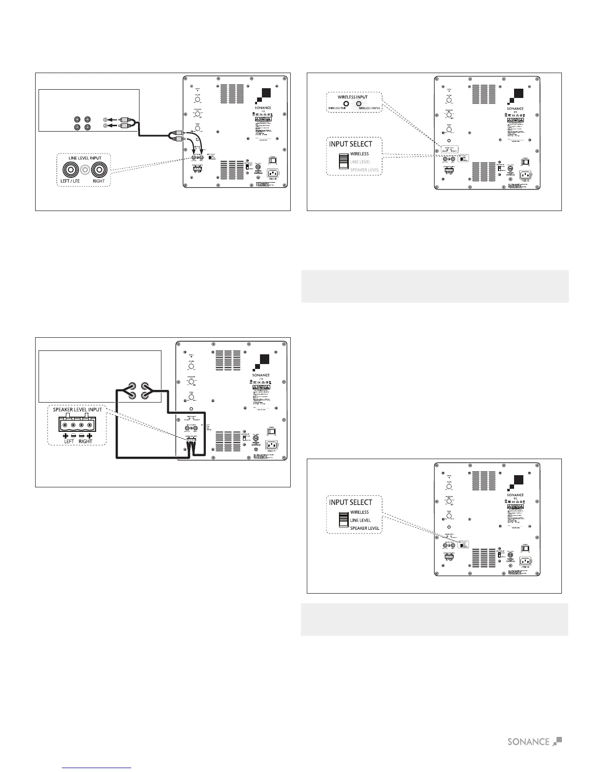
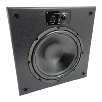
Input Select
Identify the input being utilized for the subwoofer connection and
switch the input select toggle to the appropriate input(see Figure 9).
IMPORTANT: NO SIGNAL WILL BE PASSED IF THE INPUT SELECT
BUTTON IS NOT PROPERLY SELECTED.
NOTE: IN STANDARD RESIDENTIAL CONSTRUCTION THE
SONANCE WIRELESS TRANSMITTER HAS A RANGE OF 30’.
Option 5
Wireless connectivity using the Sonance Wireless Transmitter
(see Figure 8):
Once your Sonance Wireless Transmitter and your Sonance
Subwoofer are powered on, press and release the PAIR button
located on the back of the Sonance Wireless Transmitter until the
LED light on the front of the unit blinks.
Option 3
Integrated amplifier with left and right line-level outputs but
no Main In or Amp In jacks (see Figure 6):
Use a stereo audio cable to connect the integrated amplifier’s
left and right Line Outputs to the subwoofer’s left and right LINE
INPUT jacks. If you are installing two subwoofers in the system,
connect the integrated amp’s left Line Output to the first
subwoofer’s left LINE INPUT jack and connect the integrated
amp’s right Line Output to the second subwoofer’s right LINE
INPUT jack.
Option 4
Receiver or integrated amplifier with no line-level outputs
(see Figure 7):
Use speaker wire to connect the receiver/ integrated amplifier’s
left and right speaker outputs to the subwoofer’s left and right
SPEAKER INPUTS.
FIGURE 9: SUBWOOFER ADJUSTMENTS
MAIN
OUTPUTS
Integrated
Amp
L
R
SPEAKER
OUTPUTS
Sonance
Impact Subwoofer
AUDIO CABLE
Sonance
Impact Subwoofer
(i12 shown)
Sonance
Impact Subwoofer
(i12 shown)
L R
SPEAKER
OUTPUTS
SPEAKER WIRE
Sonance
Impact Subwoofer
(i12 shown)
FIGURE 6: CONNECTING TO A INTEGRATED AMP WITH LINE OUTPUT FIGURE 8: CONNECTING USING THE SONANCE WIRELESS TRANSMITTER
FIGURE 7: CONNECTING TO A RECEIVER OR
INTEGRATED AMP WITH NO LINE-LEVEL OUTPUTS