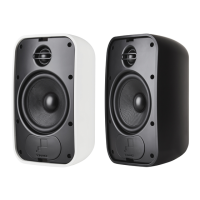
2
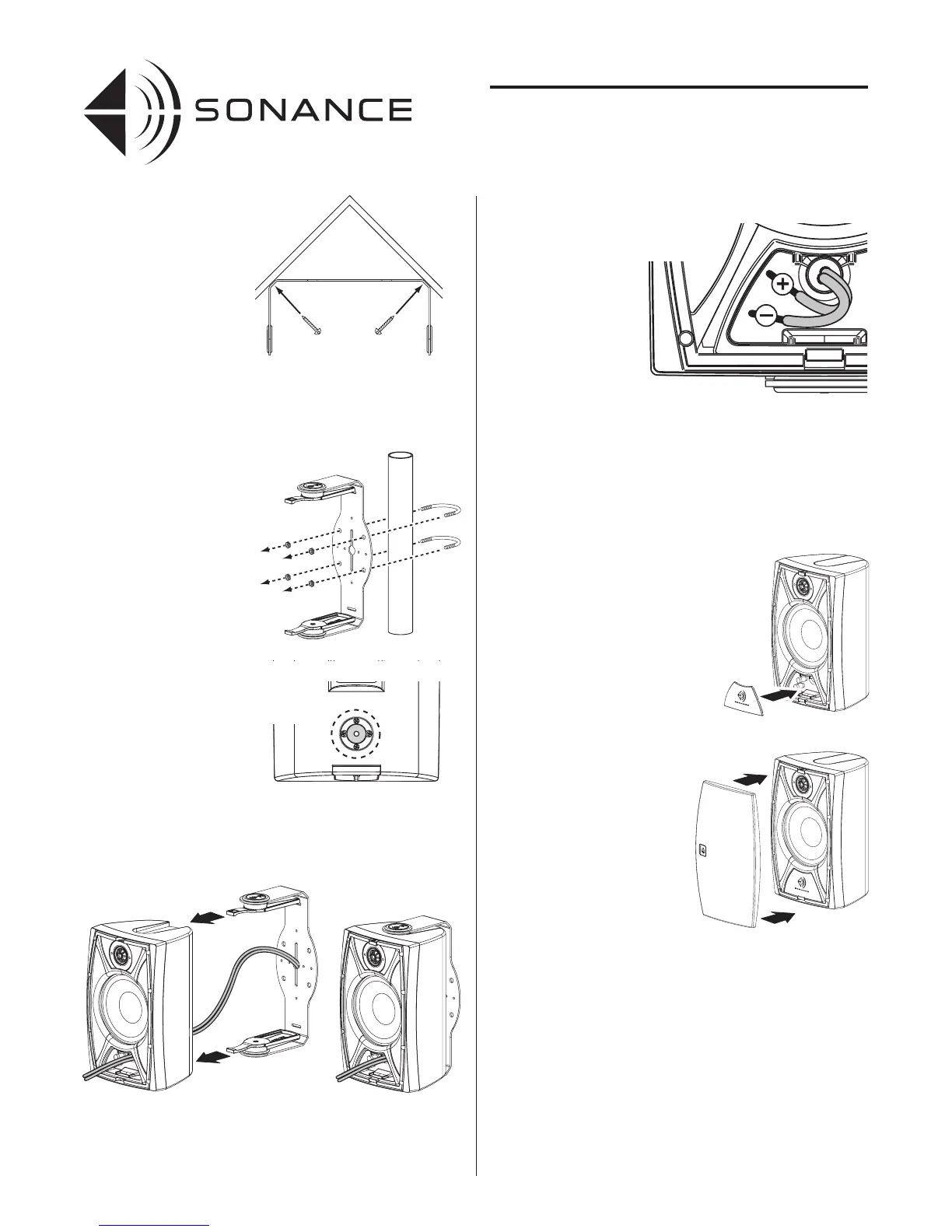
• If the installation requires
that the speakers be
mounted in a corner,
attach the brackets with
hardware through the slots
in the angled corners as
shown to the right.
Note: If the installation
requires that the speakers
be mounted vertically and
that they pivot in the
vertical dimension (or be
mounted horizontally and
pivot in the horizontal
dimension), you must
use the optional XXXX
mounting bases in addition
to the brackets.
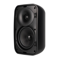
4. If the installation requires
that the speakers be
mounted on poles you can
attach the brackets to poles
using 2½” U-bolts (not
included).
5. Feed the speaker wires
from the brackets into the
wire entry grommets on
the backs of the speakers,
through the wire tunnels
and out the openings on
the speakers’ front panels.
• The grommet forms a
water-resistant seal
around the speaker wire.
• Make sure there is
enough slack in the wire
to allow the speaker to
pivot on the bracket.
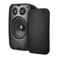
6. Slide the speakers onto the brackets until the locks snap into place.
• Pull enough wire through the front of the speaker to allow
connection to the terminals.
7. Connect the speaker wires to the speakers’ terminals:
a. Strip ¼” – ½” of
insulation from each
conductor and twist
the strands together
or tin them with
solder.
b. Press-down on the
tops of the connectors
to open them.
c. Insert the wires into
the connector holes
as shown.
d. Release the connectors.
• The binding post connectors can accept wire up to 14 gauge.
• Double-check that you connected all of the wires properly (amplifier
‘+’ to speaker ‘+’; amplifier ‘–’ to speaker ‘–’) at all connections.
IMPORTANT: Be sure not to let any stray ‘+’ and ‘–’ wires touch each
other. Touching wires can cause a short-circuit that could damage
your amplifier.
8. Fit the wiring terminal
covers into the recesses in
the speakers’ front panels.
The covers should fit tightly,
but can be removed and
replaced if the speakers
need to be disconnected.
9. Fit the grilles onto the
speakers.
• The Sonance logos can
be removed, rotated 90°
and replaced in their
centering dimples. This
maintains the correct logo
orientation on speakers
that are mounted vertically.
Note: All Sonance Mariner
speakers are compatible
with Omnimount 20.5 Series
speaker brackets. The 20.5
series includes several different
mounts that accommodate
a wide range of different
mounting requirements. For
more information contact
your Sonance Authorized
dealer or go to:
www.omnimount.com.
WIRE GAUGE
Extra resistance in the speaker wire can make a speaker sound less
dynamic and reduce definition of the bass frequencies. In extreme cases,
it can even attenuate high frequencies. Also, amplifier power is wasted in
wire with extra resistance, reducing your system’s maximum output level.
To prevent degrading sound quality, the total wire resistance should be
less than 10% of the speaker’s impedance. This means that for an 8-ohm
speaker, the total resistance of the wire should be less than 0.8 ohms.
Refer to the Wire Resistance table on page 3 when selecting the proper
wire gauge for your system:
INSTRUCTION MANUAL
SONANCE MARINER
®
SERIES
WEATHER-RESISTANT SPEAKERS
4. Attaching the
6. Attach speakers
3. Corner
 Loading...