2
SONANCE VISUAL PERFORMANCE
®
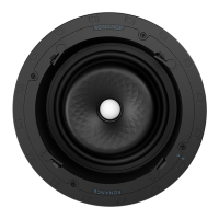
WOOFERS
Installing the Woofer
Sonance Visual Performance Series Woofers feature exclusive
FastMount tabs and an integral Roto-Lock
®
mounting system for
quick mounting directly into existing ceilings.
WARNING: THE EDGES OF THE FASTMOUNT TABS
ARE VERY SHARP. USE CAUTION WHEN HANDLING
THE WOOFER.
1. Remove the paint plug from the woofer.
2. Strip ¼” – ½” (6mm – 12mm) of insulation from each lead
of the speaker wire. Twist the strands or tin the exposed wire
with solder to ensure that there are no stray strands. (Stray
strands that touch each other can cause a short-circuit that
can damage the amplifier.)
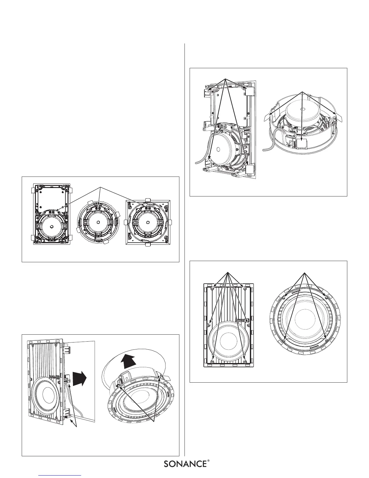
3. The woofer’s connector posts are spring-loaded. Push the top
of each connector post down to open the connector and
insert the exposed wires into the holes in the posts
(see
Figure 3
)
The woofer’s positive post is labeled with a red dot;
the negative post is labeled with a black dot. Double-check
that you connected amplifier “+” to woofer “+” and
amplifier “–” to woofer “–”.
4. Make sure all the Roto-Lock clamps are retracted so that they
are tucked within the mounting hole’s border. Insert the
woofer into the hole in the wall or ceiling (
Figure 4
).
The Roto-Lock system can accommodate a maximum wall or
ceiling material thickness of 1¼” (32mm).
The FastMount tabs will prevent the woofer from falling out
of the mounting hole, allowing the installer to let go of the
woofer to pick-up tools or other items (
Figure 5
).
NOTE: THE FASTMOUNT TABS ARE DESIGNED FOR ONE-TIME USE
ONLY. IF THE WOOFER IS REMOVED FROM THE MOUNTING HOLE
THE FASTMOUNT TABS WILL DISCONNECT AND REMAIN INSIDE
THE WALL OR CEILING.
5. Tighten the screws on the front of the woofer baffle. The Roto-
Lock clamps will automatically rotate into position and begin
clamping the woofer (
Figure 6
).
When you notice resistance on the screws the woofer has
been clamped successfully.
IMPORTANT: ALWAYS USE LOW-TORQUE SETTINGS; NEVER
OVER-TIGHTEN.
NOTE: ADJUSTING THE TENSION OF THE ROTO-LOCK CLAMPS
SO THAT THE WOOFER FRAME IS FLAT WILL HELP ENSURE THAT THE
GRILLE CONTACTS THE WALL OR CEILING ALL THE WAY AROUND
THE WOOFER FOR A PROPER FIT.