STEP 4
CONNECTING THE EQUIPMENT
1
2
3
4
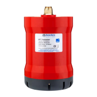
5To make sure the Transceiver has sufficient power to be able to upgrade the
firmware, an external power source can be connected to the red and black
connection points on the Test Box.
4
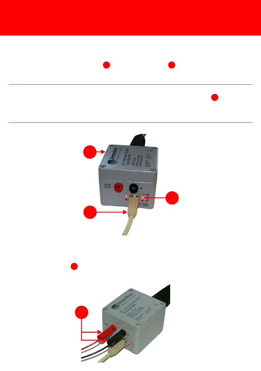
4Using a USB connection lead , connect the Test Box to a PC.
1
3
2NOTE
As soon as the Test Box is connected to the PC, the two mode lights on the Test
Box will illuminate: Red for RS232, Blue for RS485. If the mode lights do not
illuminate Red refer to the ROVNav 6 User Manual UM-8310 Section 10.3 for
details on checking the internal switches of the Test Box.
2