Do you have a question about the Sonardyne UM-8300-Compatt 6 and is the answer not in the manual?
Defines the manual's coverage and purpose for users.
Outlines information for installation, operation, and maintenance.
Lists other essential documents for safe and proper operation.
Explains formatting and typographical conventions used throughout the manual.
Emphasizes reading safety manual and warnings before operation.
Details warnings, cautions, and handling procedures for safe equipment operation.
Introduces the Type 8300 series wideband transponders and their applications.
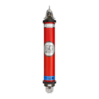
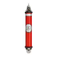
Details the features and specifications of the Compatt 6 transponder series.
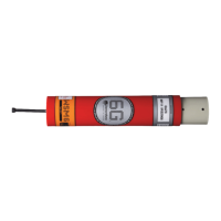
Describes various models within the Type 8300 series, like DPT, PIES, AMT, Modem, SLT.
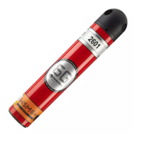
Explains the waterproof coloured labels used to identify instrument details.
Details the two types of endcaps: Transducer and Sensor, and their functions.
Describes the SubConn MCBH8F external connector and its pin configuration.
Discusses battery types, disconnect fob, and replacement procedures.
Emphasizes reading safety before proceeding with installation.
Lists essential checks before installing and operating the equipment.
Introduces common deployment methods for the transponder.
Describes how to lift the transponder using available lifting points.
Details recommended and additional methods for deploying from a ship.
Emphasizes reading safety before operating the equipment.
Explains how the transponder is activated and controlled.
Emphasizes reading safety before retrieving the equipment.
Advises on formulating a retrieval procedure for safe recovery.
Describes the process of bringing the transponder to the surface.
Lists post-retrieval steps like battery disconnect and cleaning.
Provides guidelines for proper instrument storage to maintain condition.
Emphasizes reading safety before performing maintenance.
Refers to Section 7 for retrieval procedures.
Provides instructions for cleaning the transponder after use.
Lists items to regularly inspect on the instrument for signs of damage or wear.
Recommends specific lubricants for connectors and O-rings.
Outlines recommended maintenance schedules and recalibration processes.
Explains how to operate the pressure relief vent valve for safety.
Covers checking battery condition and replacement procedures.
Step-by-step guide for removing and fitting the directional transducer endcap.
Guide for removing and fitting the omni-directional transducer endcap.
Instructions for removing and fitting the sensor endcap.
Procedures for treating minor corrosion found on the transponder housing.
Emphasizes safety and cleaning before functional testing.
Lists the necessary equipment for performing functional tests.
Describes how to perform operational checks using 6G Terminal Lite.
Guides on where to find the latest firmware and contact support.
Step-by-step instructions for updating the transponder firmware.
Procedures for updating the Data Acquisition Sub-assembly (DAS) firmware.
Assists in diagnosing and rectifying operational faults.
Lists common faults, their causes, and recommended actions.
Provides information on ordering spare parts.
Lists common spare parts including batteries, upgrade kits, and miscellaneous items.
Provides mechanical dimensions and specifications for the Compatt 6.
Details mechanical specifications for the Mini Compatt 6.
Lists mechanical specifications for the Midi Compatt 6.
Provides mechanical specifications for the Maxi Compatt 6.
Presents data on battery capacity, voltage, and estimated life.
Introduces an app for estimating transponder battery life.
Details the RS232 communication port and baud rates.
Specifies acoustic transducer types, frequency range, and sensitivity.
Lists operating and storage temperature ranges and IP rating.
Provides specifications for temperature and depth sensors.
Details parameters for the responder input trigger and commands.
Defines and provides an example calculation for net upthrust.
Refers to outline drawings for Compatt 6 and variants.
Explains the hardware and principles of Long Baseline positioning systems.
Describes Short Baseline positioning systems, their hardware, and principles.
Details Ultra-short Baseline positioning systems, including hardware and principles.
Explains L/USBL systems as a special case of USBL with improved accuracy.
Describes LSUSBL as a combination of USBL, LBL, and SBL modes.
Lists compatible transceivers and their applications.
Explains remote control of transponder modes via acoustic signals.
Describes configuration and testing via RS232 link with PC software.
| Type | Acoustic Transponder |
|---|---|
| Operating Temperature | -5°C to +40°C |
| Storage Temperature | -20°C to +60°C |
| Transducer Beam Width | Omnidirectional |
| Power Supply | Lithium battery pack |