Do you have a question about the Sonatest Masterscan D-70 and is the answer not in the manual?
Provides essential safety guidelines for using ultrasonic test equipment.
Highlights potential hazards related to the Masterscan D-70's pulser circuitry.
Emphasizes the need for adequate operator training in ultrasonic testing procedures.
Details the importance of sound velocity calibration for accurate distance/thickness readings.
Explains the necessity of transducer zero and calibration for accurate readings.
Discusses factors affecting flaw detection amplitude and calibration methods.
Advises performing calibrations at consistent temperatures to minimize errors.
Specifies requirements for transducer condition and material testing temperature.
Guides on proper couplant usage to ensure accurate readings and minimize errors.
Outlines the structure and content of the user's guide.
Explains symbols and conventions used throughout the manual.
Defines typographical conventions for screen text, italics, and keys.
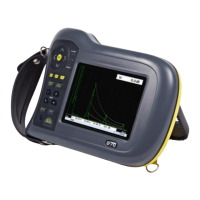
Welcomes the user and introduces the Masterscan D-70 device.
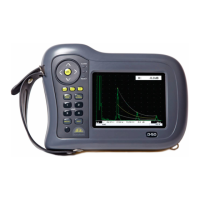
Describes the Masterscan D-70 as a user-friendly digital flaw detector and thickness gauge.
Lists the various ultrasonic testing methods supported by the device.
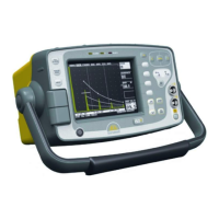
Details the main controls and navigation features of the Masterscan D-70's front panel.
Identifies connectors and components located on the back panel of the device.
Explains how settings are retained in memory when the instrument is off.
Provides steps to reset the instrument's settings to factory defaults.
Describes the function and purpose of each button on the Masterscan D-70.
Explains how to navigate and select main menu options on the device.
Lists the items accessible within each main menu (Cal, Meas, Mem, Util).
Details the calibration options available in the CAL menu.
Explains probe zero, velocity, range, and delay calibration parameters.
Describes filter, detect, reject, and mode settings for signal amplification.
Covers pulse width, damping, edge, voltage, and PRF settings for the transmitter.
Explains the configuration of gates for triggering and measurement.
Describes the automated calibration feature for sound velocity and transducer zero.
Details the configuration of parameters for the interface trigger functionality.
Introduces menus for various measurement techniques.
Describes different measurement modes like Monitor, Depth, E-E, and Trigonometry.
Explains how to set up temperature compensation for measurements.
Introduces options for flaw sizing techniques like DAC, TCG, AVG, AWS, and API.
Details the procedure for creating and using DAC curves for flaw sizing.
Explains the TCG feature for compensating material attenuation.
Describes the DGS/AVG method for flaw sizing and distance compensation.
Details the API 5UE method for evaluating pipe imperfections.
Explains the AWS method for evaluating weld discontinuities.
Describes the B-Chart measurement mode for internal wall profiling.
Covers storage and recall of calibration settings and A-scans.
Details saving and loading of panel configurations and settings.
Explains storing and recalling A-scans with their associated settings.
Describes displaying stored A-scans as reference waveforms.
Introduces thickness logging options.
Explains the Grid Log feature for thickness logging.
Describes configuring and saving grid plans for thickness logging.
Covers language, units, and customization options.
Covers language, units, and customization options.
Details settings for signal display contour, smoothing, and fade rate.
Explains how to assign functions to user-definable buttons.
Covers pulse mode, alarm, and keylock settings.
Describes display color schemes and brightness settings.
Explains the function of the backwall echo attenuator.
Details the automatic gain control feature for thickness logging.
Covers encoder setup for resolution and direction.
Explains how to set and display the instrument's time and date.
Guides on storing and recalling instrument calibration settings.
Covers essential considerations for reliable flaw detection.
Explains the process of setting pulser, amplifier, and gate parameters for flaw detection.
Outlines key considerations for accurate and reliable thickness gauging.
Details the steps for calibrating the instrument for thickness testing.
Explains the automated calibration feature for thickness gauging and depth measurement.
Describes the Time Corrected Gain feature to improve echo consistency.
Discusses thickness logging capabilities and limitations.
Explains how DAC curves compensate for attenuation and beam characteristics.
Details the temperature compensation feature for accurate measurements.
Describes using trigonometry mode for locating discontinuities in welds.
Explains the Flank-Flank measurement mode for thickness gauging.
Covers storing, recalling, and printing A-scans with instrument settings.
Explains techniques for enhancing echo visibility and capturing peak data.
Details the B-Chart functionality for graphical wall profiling.
Describes the process for storing and managing B-Charts.
Explains the USB connector for PC data transfer and software updates.
Describes the encoder connection for data acquisition.
Guides on activating optional features using license keys.
Details the TCG feature for compensating material attenuation.
Explains the DGS/AVG method for flaw sizing and distance compensation.
Covers frequency, near field length, and equivalent reflector size settings.
Details settings for transfer loss and material attenuation.
Explains curvature correction, reference type, and reflector size settings.
Describes the calibration process for the DGS/AVG system.
Covers adjusting parameters like gain after DGS/AVG calibration.
Explains how to use the DGS/AVG system to calculate equivalent reflector size.
Details the AWS method for evaluating weld discontinuities.
Explains the API 5UE method for pipe imperfection assessment.
Refers to a separate manual for details on grid thickness logging.
Discusses immersion testing and its challenges.
Highlights issues encountered in immersion testing with ultrasonic detectors.
Explains the principles and advantages of dry coupling.
Describes the characteristics of transducers used in dry coupling.
Explains the operational mechanism of the dry coupling system.
Guides on interpreting results obtained from dry coupling analysis.
Describes the Lithium-Ion battery pack for the Masterscan D-70.
Lists important safety precautions for handling Lithium-Ion batteries.
Provides instructions and cautions for charging the battery pack.
Details specific warnings regarding battery charging procedures.
Describes the Sonatest CH700-P battery charger and its specifications.
Addresses issues related to the unit not powering on.
Explains the meaning of the charger's LED indicator colors.
Provides troubleshooting steps for reduced battery life.
Offers solutions for a malfunctioning scroll wheel.
Guides on interpreting and resolving on-screen warning or error messages.
Troubleshoots problems with data storage and recall.
Provides solutions for intermittent or permanent unit freezes.
Addresses issues with weak or absent signals on the A-scan display.
Offers troubleshooting steps for faulty or snowy display output.
Provides information on how to contact Sonatest for further assistance.
Provides guidelines for cleaning and protecting the instrument's casing.
Offers instructions for cleaning and protecting the display screen.
Advises on precautions to take when transporting the unit.
| Brand | Sonatest |
|---|---|
| Model | Masterscan D-70 |
| Category | Test Equipment |
| Language | English |