Slot 3 x8 (x4)
Slot 1 x8 (x8)
Slot 2 x16 (x8)
4
Chapter 3 – PCIe Card Installation and Chassis Setup Steps
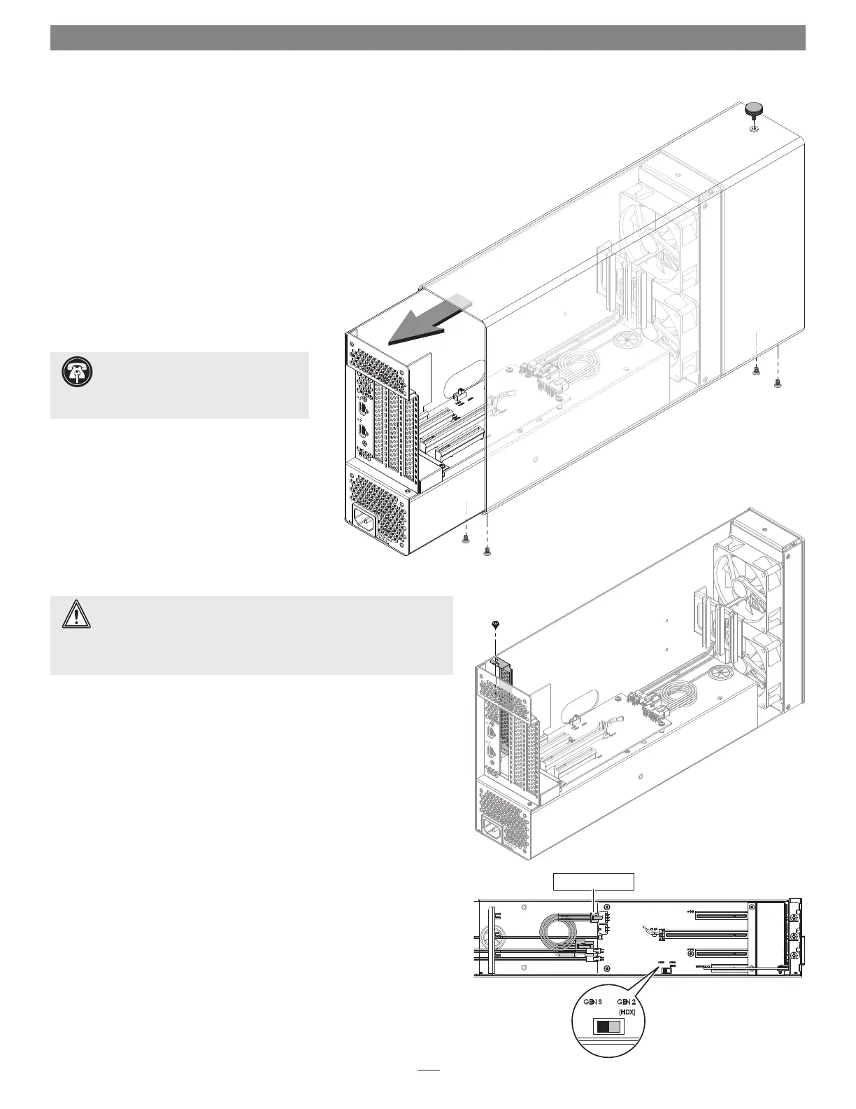
Figure 2
1. Remove the Echo III Desktop from its packaging, and then set it on a
flat, level surface.
2. Using a Phillips screwdriver, remove and set aside the four screws
securing the bottom of the enclosure to the Echo III Module
(Figure 1).
3. Unscrew and set aside the thumbscrew securing the top of the
enclosure to the module (Figure 1).
4. Grasping the enclosure with one hand, push the front of the
module part way into the enclosure, and then gently pull
the module out the back (Figure 1). Set aside the
enclosure.
5. Remove and set aside the screw securing a PCIe
slot cover to the module (Figure 2).
6. Remove and set aside the loose PCIe slot access
cover (Figure 2).
7. If you are installing more than one card, repeat steps
5 and 6 as necessary with the remaining slot access covers.
8. OPTIONAL STEP 1: If you are not installing a PCIe card which requires
auxiliary power, go to step 10. Otherwise, locate the auxiliary power
cable connected to the indicated 6-pin connector (Figure 3).
• When installing Pro Tools | HDX PCIe cards, disconnect and set aside
the power cable, replace it with the custom power cable included
with an Avid card, and then move the loose connectors aside for later
connection.
• When installing cards other than the Pro Tools | HDX, remove the
cable twist tie securing the power cable, and then move the loose
connector aside for later connection.
9. OPTIONAL STEP 2: If you are installing Avid Pro Tools | HDX cards,
move the Gen 3/Gen 2 (HDX) switch (Figure 3) to the Gen 2 (HDX)
position to enable compatibility. Otherwise, the card(s) will not work
in the Echo chassis.
Support Note: To avoid damaging
components due to static electricity
discharge, wear an antistatic wrist strap while
working inside the Echo chassis.
WARNING: When handling computer products, take care to prevent
components from being damaged by static electricity; avoid working
in carpeted areas. Handle expansion cards only by their edges and avoid
touching connector traces and component pins. Also, avoid touching the
Echo chassis’ circuit boards and any of its components.
Figure 3
Figure 1
6-pin connector